
Installation Instructions

g009053
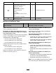
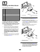
Figure7
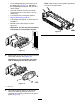
1.Removethenutssecuring
eachendoftheroller.
3.Side-platemountingange
2.6mm(1/4inch)spacer
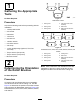
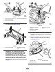
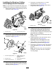
7.Positiontheroller-brushmountingbracketsonto
theroller-bracketbolts(Figure8).
g009054
Figure8
1.Rollerbrushassembly2.Roller-brushmounting
bracket
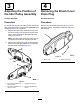
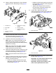
Important:Theroller-brushmounting
bracketsmustbemounteddirectlytothe
topsurfaceofthecutting-unitside-plate
mountingange.Donotputspacers
betweentheroller-brushmountingbrackets
andtheside-platemountinganges.Install
additional6mm(1/4inch)spacersonthe
topsideoftheroller-brushmountingbracket
(Figure9).
g009055
Figure9
1.Roller-brushmounting
bracket
3.Extra6mm(1/4inch)
spacer
2.Cutting-unitside-plate
mountingange
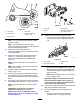
8.Securetheroller-brushmountingbracketstothe
cutting-unitsideplateswiththenutspreviously
removed.
9.Slideeachexcludersealoutwarduntilthelip
sealsareinlightcontactwitheachbearing
housing(Figure10).
g009056
Figure10
1.Excluderseal3.Mountingbracket
2.Bearinghousing
6