
Installation Instructions
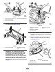
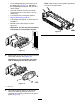

10.Applyacoatingofgreasetotheinnerdiameter
ofthegrommetinthebearinghousing(Figure
11).
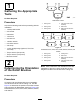
g009057
Figure11
1.Shoulderbolt
5.Roller-brushmounting
bracket
2.Brushplate6.Flangelocknuts
3.Bolt7.Roller-brush-bearing
housing
4.Grommetinbearing
housing
11.Loosen,butdonotremove,theboltssecuring
theroller-brush-bearinghousingtothe
roller-brushmountingbracket(Figure11).
12.Installtheroller-brushpivotplate(Figure11).
Note:Whenyouinserttheprotrusiononthe
pivotplateintothegrommetinthebearing
housing,ensurethatthegrommetstaysproperly
seatedinthehousing.
Note:Theroller-brushpivotplateisproperly
seatedwhenthereisnoresistancefromthe
rubbergrommetanditpivotsfreely.
13.Apply243Loctite(blue)tothe2bolts(5/16x5/8
inch)andusethemtomountthebrushplateto
theroller-brush-bearinghousing(Figure11).
Note:T orquetheboltsto20to25N∙m(15to
19ft-lb).
14.Checktomakesurethattheroller-brushplateis
paralleltothecutting-unitsideplate.Ifitisnot
parallel,proceedasfollows:
•Loosenthe2angelocknutssecuringthe
roller-brushmountingbrackettothecutting
unitsideplate(Figure11).
•Rotatetheroller-brush-bearinghousinguntil
thebrushplateisparalleltothecutting-unit
sideplate(Figure11).
•Tightenthe2angelocknutssecuring
theroller-brushmountingbrackettothe
cutting-unitsideplate(Figure11).
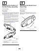
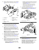
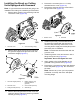
15.Loosenthe2boltssecuringeach
roller-brush-bearinghousingtotheroller-brush
mountingbracket(Figure12andFigure13).
g009078
Figure12
1.Loosenthesebolts.
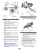
g009079
Figure13
1.Loosenthesebolts.
16.Positiontherollerbrushsothatitjusttouches
therearroller(Figure14).
Important:Theroller-brushshaftmustnot
contactthecutting-unitside-plate.
Important:Heavybrushcontactonthe
rollercausesprematurebrushwear.
7