
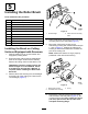
Installation Instructions
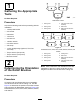

g029308
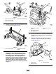
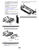
Figure14
1.Side-plate
4.Rearroller
2.Rollerbrush5.Ensurethatthereis
clearancehere.
3.Lightcontact
Note:Therollerbrushshaftmustbeparallel
totherearroller.
Note:Theorientationofthenon-drive
roller-brush-bearinghousingshouldbethesame
asdrive-sidebearinghousing.
17.Tightenthe2boltssecuringeach
roller-brush-bearinghousingtotheroller-brush
mountingbrackets.
18.Apply243Loctite(blue)totheshoulderbolt
(Figure11).Securethebrushplatetothe
roller-brushhousingwiththeshoulderbolt.
(Figure11).
Note:Torquetheboltto20to25N∙m(15to
19ft-lb).
Note:Theshoulderboltshouldnotclampthe
platetothehousing.
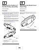
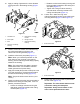
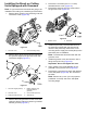
19.Installthespacerontotheshaftinthebearing
housing(Figure15).
20.Insertthedrivepulleyintothespacerandonto
thedriveshaft(Figure15).Makesurethatthe
pulleytabsarepositionedintheslotinthedrive
shaft.
21.Securethepulleyandspacertothedriveshaft
withaange-headbolt(3/8x2inch)(Figure15).
Note:Torquetheboltto47to54N∙m(35to
40ft-lb).
Important:Iftheboltisnotproperly
torqued,theboltwillcomeloose.
Restrainthereelforinstallation;referto
RestrainingtheReelforInstallingThreaded
Inserts(page18).
g009058
Figure15
1.Driveshaft
3.Drivepulley
2.Spacer
4.Bolt—torqueto47to54
N∙m(35to40ft-lb)
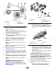
22.Installthebeltontothepulleysasfollows:
•Loopthebeltaroundthedrivenpulleyand
thenoverthetopoftheidlerpulley(Figure
16).
g009059
Figure16
1.Drivepulley3.Drivenpulley
2.Idler-pulleyassembly4.Belt
•Startthebeltonthedrivepulley(Figure16).
•Whileguidingthebeltontothedrivepulley,
rotatethereelforwardtodrawthebeltonto
thedrivepulley.
Note:Wearapaddedgloveoruseaheavy
ragtorotatethereel.
Important:Makesurethattheribsonthe
beltareproperlyseatedinthegroovesin
eachpulley.Also,makesurethatthebeltis
inthecenteroftheidlerpulley.
23.Pushdownontheidlerpulleytoensurethatthe
idlerpulleyassemblypivotsfreely.
24.Checkthealignmentofthebelt/pulleysas
follows:
•Thebeltmustbeproperlytensioned
(installed)priortocheckingalignment.
8