
Installation Instructions


PreparingtoInstallthePTO
SwitchKit
WARNING
Batteryterminalsormetaltoolscouldshort
againstmetalcomponent,causingsparks.
Sparkscancausethebatterygassesto
explode,resultinginpersonalinjury.
•Whenremovingorinstallingthebattery,
donotallowthebatteryterminalstotouch
anymetalpartsofthemachine.
•Donotallowmetaltoolstoshortbetween
thebatteryterminalsandmetalpartsofthe
machine.
WARNING
Incorrectbatterycableroutingcoulddamage
themachineandcables,causingsparks.
Sparkscancausethebatterygassesto
explode,resultinginpersonalinjury.
•Alwaysdisconnectthenegative(black)
batterycablebeforedisconnectingthe
positive(red)cable.
•Alwaysconnectthepositive(red)battery
cablebeforeconnectingthenegative
(black)cable.
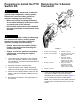
1.Locatethewiringschematicforyourmachine;
refertotheOperator’sManual,PartsCatalog,
ServiceManual,orElectricalSchematicManual
foryourproduct.
2.Movethemachinetoalevelsurface.
3.Lowerthecuttingunits,engagetheparking
brake,shutofftheengine,andremovethekey.
4.Disconnectthenegative-batterycablefromthe
battery;refertotheOperator’sManualforyour
machine.
5.AccessthePTOswitchinthecontrolpanelof
themachine.
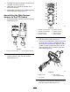
Removingthe5-Socket
Connector
g234470
Figure1
1.Contact—circuit-C(tape)6.Contact—circuit-A
2.Contact—circuit-B(tape)7.5-socketconnector—PTO
switch(machinewire
harness)
3.Blank8.Tapewiremarker
(5-socketconnector)
alignedwiththePTO
switchcircuitBcontact
4.Contact—circuit-D
9.Tapewiremarker
(5-socketconnector)
alignedwiththePTO
switchcircuitCcontact
5.Contact—circuit-E
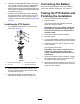
1.Inthecircuitidenticationtablethatfollows,
recordtheinsulationcolorsforthewires
assembledtothe5-socketconnector(Figure1)
fortherelatedPTOswitchcontactletters:
Note:Yourmachinemayhaveeither4wiresor
5wiresatthe5-socketconnectorforthePTO
switch.
2