
Installation Instructions


CircuitIdenticationTable
Switch
contact
circuits
Recordthewireinsulationcolorinthespace
below:
Z(example)PINK(example)
A
B(markthe
5-socket
connector
wire)
C(markthe
5-socket
connector
wire)
D
E
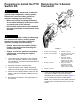
2.Useelectricaltapetomarkthewiresofthe
5-socketconnectoralignedwiththePTOswitch
circuitBandCcontacts(Figure1).
3.Removethe5-socketconnectorfromthePTO
switch.
RemovingthePTOSwitch
1.Removethejamnutandlockinternal-tooth
washerthatsecuresthePTOswitchtothe
controlpanel.
2.RemovethePTOswitchfromthecontrolpanel.
InstallingtheAdapterWire
Harness
PreparingtheAdapterWire
Harness
Note:TheAdapterwireharnesshaswireswith
insulationcolorsforavarietyofmachines.Youneed
nomorethan5wiresoftheadapterwireharness.
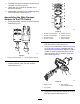
1.Identifythewirecolorsoftheadapterwire
harnessthatarenotinthemachinewireharness
atthe5-socketconnectorforthePTOswitch
(Figure2).
g234487
Figure2
1.Adapterwireharness
3.5-socketconnector—PTO
switch(machinewire
harness)
2.Removedwires
2.Removethewireswithinsulationcolorsthatyou
foundinstep1.
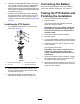
InstallingtheHarnessAdapter
1.Atthe5-socketconnectorforthePTO,cutthe
wiresclosetotheconnector(Figure3).
g234548
Figure3
1.5-socketconnector
3.10mm(3/8inch)
2.Butt-spliceconnectors
4.Wire(PTOswitchcircuit)
2.Strip9mm(3/8inch)oftheinsulationsfromthe
endsofthewiresthatyoucutinstep1.
3.Matchtheinsulationcolorofthewiresyou
stripedinstep2totheinsulationcolorofwires
inthewire-harnessadapter(Figure3).
3