
Installation Instructions
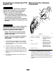


4.Insertthewireintothebutt-spliceconnectorand
crimptheconnector(Figure3).
5.Useaheatguntoshrinktheinsulatorofthe
butt-spliceconnector
6.Repeatsteps3through5fortheremainingwires
ofthePTOswitchcircuits(Figure3).
AssemblingtheWire-Harness
AdaptertothePTOSwitch
1.IdentifythekeywayslotsinthenewandoldPTO
switches(Figure4).
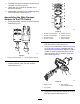
g234571
Figure4
1.Keyway(newPTOswitch)2.Keyway(oldPTOswitch)
2.Withthekeywayslotsaligned,identifythe
contactlocationsofthenewandoldPTO
switches(Figure5).
g234570
Figure5
1.Contact—circuit-C(tape)5.Contact—circuit-E
2.Contact—circuit-B(tape)6.Contact—circuit-A
3.Notused—blank
7.NewPTOswitch
4.Contact—circuit-D8.OldPTOswitch
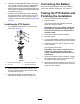
3.RemovethescrewandlockwasherforcircuitB
fromthenewPTOswitch(Figure5).
4.UsingthecircuitidenticationtableinRemoving
thePTOSwitch(page3),assemblethering
terminalsofthewire-harnessadapterforswitch
contactcircuitsB(markedwithtape)ontothe
newPTOswitchwiththemachinescrewand
lockwasher(Figure6).
g234569
Figure6
1.Machinescrew3.Ringterminal
(wire-harnessadapter)
2.Lockwasher
5.RemovethescrewandlockwasherforcircuitC
fromthenewPTOswitch(Figure5).
4