
Installation Instructions

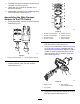


6.UsingthecircuitidenticationtableinRemoving
the5-SocketConnector(page2),assemblethe
ringterminalsofthewire-harnessadapterfor
switchcontactcircuitsC(markedwithtape)onto
thenewPTOswitchwiththemachinescrewand
lockwasher(Figure6).
7.Usingthecircuitidenticationtable,assemble
theringterminalsforcontactcircuitsA,D,and
ifapplicableEtothenewPTOswitchwiththe
machinescrewsandlockwashers(Figure5and
Figure6).
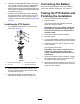
InstallingthePTOSwitch
1.Ifnotinstalledthreadajamnutontothenew
PTOswitch(Figure7).
g234593
Figure7
1.Keynotch(controlpanel)
3.Internal-toothwasher
2.Jamnuts
4.Keyway(PTOswitch)
2.Alignthekeywayoftheswitchwiththekeyin
theopeningofthepanel,andinserttheswitch
intothepanel(Figure7).
3.Assembletheswitchtothepanelwiththe
internal-toothwasherandjamnut(Figure7).
ConnectingtheBattery
Connectthenegative-batterycabletothebattery;
refertotheOperator’sManualforyourmachine.
TestingthePTOSwitchand
FinishingtheInstallation
1.SetthePTOswitchtotheONposition.
2.Starttheengine.
TheengineshouldnotstartwhenthePTO
switchisintheONposition.
Important:Iftheenginestarts,engagethe
parkingbrake,shutofftheengine,remove
thekey,andcheckthewireconnectionsat
thePTOswitch.
3.SetthePTOswitchtotheOFFposition.
4.Starttheengine.
5.CyclethePTOswitchtotheONandOFFposition
severaltimestocheckthefunctionoftheswitch.
6.SetthePTOswitchtotheONpositionandlift
outoftheseat.
Theengineshouldshutoff.
Important:Iftheenginecontinuestorun,
engagetheparkingbrake,shutoffthe
engine,removethekey,andcheckthewire
connections.
7.SetthePTOswitchtotheOFFposition,engage
theparkingbrake,movethekeyswitchtothe
OFFposition,andremovethekey.
8.Assemblethecontrolpanelthatyouremovein
step5ofPreparingtoInstallthePTOSwitchKit
(page2)tothemachine.
5