
Installation Instructions
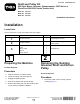


g016238
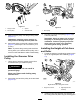
Figure6
1.Drivenpulley3.Flangelocknut
2.Groomingshaft
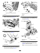
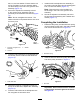
7.Removethegroomerdrivepulleyfromthereel
shaft(Figure7).
g016239
Figure7
1.Groomerdrivepulley
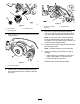
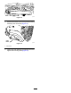
8.Removethe2shoulderboltsthatsecurethe
drive-plateassemblytothecutting-unitframe
(Figure8).
g016240
Figure8
1.Groomer-drive-plate
assembly
2.Shoulderbolts
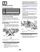
9.Removethegroomer-drive-plateassembly
(Figure8)fromthegroomingshaftandcutting
unit,andlocateandretrievethegroomershim.
Note:Thegroomershimislocatedbetween
thedrive-plateassemblyandthecutting-unit
sideplate.Youmayneedtoretrieveitwhenyou
removethedrive-plateassembly.
10.Carefullypullthegrooming-shaftassemblyfrom
theleftsupportplate.
Note:Theshaftassemblycanbediscarded.
11.Inspectthefollowingcomponentsforwearor
damage:
•Seals,bushings,andbearingsinthedrive
plate,supportplate,andgroomerarms.
•Pulleysandidlercomponents.
Replacethesecomponentsasneeded.
3