
Installation Instructions
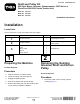
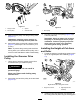


g291253
Figure11
1.Flangelocknut
3.Spacer
2.Drivenpulley
4.Groomershaft
9.Slidethedrivenpulleyontothegroomingshaft
(Figure11).
Important:Installthepulleycarefullyso
thatyoudonotdamagetheside-plateseal.
10.Securethepulleytoshaftwithaangelocknut
(Figure11)andtorqueitto23to28N∙m(17to
21ft-lb).
Note:Topreventthegrooming-reelshaftfrom
turningwhenyouinstallthedrivenpulley,usea
wrenchontheshaftatstoholdtheshaftsteady.
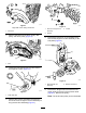
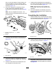
InstallingtheGroomerDrive
Pulley
1.Useapieceofwoodtopreventthereelfrom
movementwhileyouinstallthepulley.
WARNING
Contactwiththereelcanresultin
personalinjury.
Keepyourngersandclothingaway
fromthereel.
2.Securethegroomerdrivepulleytothereelshaft
(Figure12).
g016218
Figure12
1.Drivepulley
3.Torquethegroomerdrivepulley(Figure12)to
170N∙m(125ft-lb).
Important:Usinganimpactguntotorque
thepulleyisnotenoughtoensureproper
installation.Failuretoproperlytorquethe
drivepulleycanresultintheassembly
unscrewingitselfduringoperation.
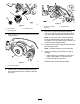
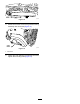
InstallingtheHeight-of-CutArms
andRoller
1.Threadtheheight-of-cutadjustingscrewintothe
topoftheright-adjuster-armassembly(Figure
13).
g016216
Figure13
Rightsideofthecuttingunitshown
1.Height-of-cutscrew
2.Right-adjuster-arm
assembly
2.Installtheright-handadjuster-armassemblyto
thecutting-unitsideplateusingtheexistingplow
5