
Installation Instructions
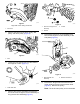
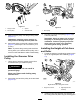


bolt,nut,andnewwasher.Ensurethattherod
endoftheheight-of-cutarmassemblyslides
intothebushingintheholeinthegroomerdrive
assembly(Figure13).
3.Securetheadjuster-armassembly-rodend
tothegroomerdriveassemblywiththe
previously-removedwasherandlocknut(Figure
14).
Note:Donotovertightenthelocknut.The
washershouldbecompressedbutthearmmust
befreetopivot.
g016217
Figure14
1.Rodendofheight-of-cut
assembly
3.Washer
2.Locknut
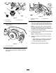
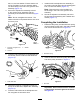
4.Inserttherollershaftintotherightadjusterarm
andlooselysecureitwiththeroller-shaftbolt
(Figure15).
g016229
Figure15
1.Rollershaftbolt
5.Threadtheheight-of-cutadjustingscrewinto
thetopoftheleft-hand,adjuster-armassembly
(Figure13).
6.Inserttherollershaftintotheleftadjusterarm.
Donottightentheboltatthistime.
7.Installtheleft-handadjuster-armassemblyto
thecutting-unitsideplateusingtheexistingplow
bolt,nut,andnewwasher(Figure13).
Note:Ensurethattherodendslidesinto
thebushingintheholeinthegroomerdrive
assembly.
8.Securetheadjuster-armassembly-rodendto
thegroomerdriveassemblywithawasherand
locknut(Figure14).
CompletingtheInstallation
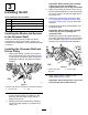
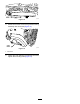
1.Rotatetheidlerpulleyuntiltheshift-leverspring
canbehookedintotheholeinthepulleybracket
andontothestudasshowninFigure16.
g016230
Figure16
1.Shift-leverspring
2.Insertthebeltontothedriverpulley,idlerpulley,
anddrivenpulleyasshowninFigure17.
g016231
Figure17
1.Drivebelt
Important:Ensurethatthebeltiscentered
onthepulleysandinthegroovesasshown
inFigure18.
6