
Installation Instructions
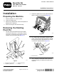


5.Whenthepivotpinisremovable,removethe
bolt,washer,andpivotpin(Figure4).
g283508
Figure4
1.Bolt(1/2x3-1/4inch)
3.Pivotpin
2.Washer
6.Repeatsteps3through5fortheotherpivotpin.
7.Checkthepivotbushingsoftheattachment
mountplateforwearordamage.Replaceany
asnecessary.
InstallingtheNewPivot
Pins
1.Installthegreasettingsontothenewpins.
2.Aligntheholesintheloaderarmswiththeholes
intheattachmentmountplate.
3.Onbothsidesoftheattachmentmountplate,
slidethetaperedendofthepivotpinintothe
holesfromtheinsideoftheattachmentmount
plate.
g283514
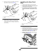
Figure5
1.Bolt(1/2x3-1/4inch)
3.Pivotpin
2.Washer
4.Ensurethatthetaperonthepinsandtheholes
arecleanandfreeofgrease.
5.Applythread-lockingcompoundtothebolts(1/2
x3-1/2inches),andsecureeachpinwithabolt
andwasherasshowninFigure5.T orquethe
boltsto127to157N∙m(94to116ft-lb).
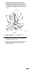
6.Rotatetheattachmentmountplateuptoward
theloaderarms(Figure6).
g283517
Figure6
2