
Installation Instructions
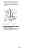


7.Insertthehydrauliccylinderrodsintothe
attachmentmountplateandsecurethemwith
thelinkpins,bolts(5/16x2-1/2inches),and
locknuts(5/16inch)removedpreviously(Figure
7).Torquethelocknutsto20to25N∙m(15to
18ft-lb).
g283507
Figure7
1.Bolt(5/16x2-1/2inches)3.Locknut(5/16inch)
2.Hydrauliccylinderrod4.Linkpin
8.Greasethebaseandrodendofthehydraulic
cylindersandthepivotpins.
9.Startthemachineandtilttheattachmentmount
plateforwardandrearwardtoverifythatit
operatesproperly.
3