
Installation Instructions


3
InstallingtheHydraulic
Tubes
Partsneededforthisprocedure:
1
Straighttting
1
Tubewithcentertting
1
Tubewithextraendtting
1Tube
1Bulkheadtube
1
Elbowtting
Procedure
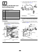
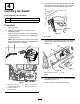
1.Disconnectthehoseandelbowttingfromport
A2(bottom,middle)ontheliftvalve(Figure4).
g312131
Figure4
1.HosefromportA2(bottom,
middle)
3.PortA2(bottom,middle)
2.Tubewithcentertting
2.InstallastraightttingtoportA2(bottom,
middle).Torquethettingto94to115N∙m(69
to85ft-lb).
3.Installthetubewithcenterttingfromport
D(left)ontheself-levelingvalvetoportA2
(bottom,middle)ontheliftvalve(Figure4).
4.Installthehosethatyoudisconnectedtothe
ttingonthetube.
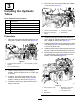
5.DisconnectthehosefromportB2(top,middle)
ontheliftvalve(Figure5).
g312132
Figure5
1.Tubewithextraendtting3.PortB2(top,middle)
2.HosefromportB2(top,
middle)
4.Elbowtting
6.Installthetubewiththeextraendttingfrom
portC(right)ontheself-levelingvalvetoportB2
(top,middle)ontheliftvalve(Figure5).
7.Installtheelbowttingtothetubewiththeextra
endtting(Figure5).Torquethettingto94to
115N∙m(69to85ft-lb).
8.Installthehosethatyoudisconnectedfromport
B2(top,middle)totheelbowttingonthetube.
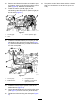
9.Markanddisconnecttheleftcylinderhosefrom
thetubeandtherightcylinderhosefromthe
bottomofthebulkhead(Figure6).
g312148
Figure6
1.PortA1(bottom,right)
4.Bulkhead,connectedto
rightcylinderhose
2.Tube
5.Leftcylinderhose
3.Mountplate
3