
Installation Instructions


4
InstallingtheSwitch
Partsneededforthisprocedure:
1
Switch
1Wireharness
Procedure
1.Openthehood.
2.Plugthewireharnessinthebackofthe
self-levelingvalve.
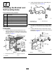
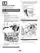
3.Plugtheaccessorypower-inconnector(P03)
toanaccessoryconnectoronthemachinewire
harness(Figure9).
Note:Usetheaccessorypower-outconnector
(P04)onthewireharnesstoconnectadditional
kitstothemachine,ifneeded.
g312400
Figure9
1.Accessorypower-out
connector(P04)withcap
3.Accessoryconnectoron
machinewireharness
2.Accessorypower-in
connector(P03)
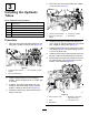
4.Routethewireharness,followingthemachine
wireharness,throughtheholeontheleftside
towardthefrontofthemachine(Figure10).
g312402
Figure10
1.Wireharness
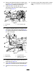
5.Removethesecondplugfromthecontrolpanel,
androutethewireharnessthroughthehole
(Figure11).
g312401
Figure11
1.Switchconnectoronwire
harness
2.Switch
6.Plugthewireharnessintotheswitchandinstall
theswitch(Figure11).
7.Closethehoodandrear-accesscover.
5