Form No 3359-793 Rev A Count on it. LX426 Lawn Tractor m Model No. 13RL60RG044 Model No. 13RL60RG244 Model No. 13AL60RG048 0 O. 0 Register your product at www.Toro.
California Proposition 65 Warning: WARNING: Engine exhaust, some of its constituents, and certain vehicle components contain or emit chemicals known to the State of California to cause cancer and birth defects or other reproductive harm.
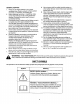
SECTION1: IMPORTANT SAFEOPERATION PRACTICES WARNING: This symbol points out important safety instructions which, if not followed, could endanger the personal safety and/or property of yourself and others. Read and follow all instructions in this manual before attempting to operate this machine. Failure to comply with these instructions may result in personal injury. When you see this symbol-heed its warning.
DO: 21. Neverleavea runningmachineunattended. Alwaysturnoffblade(s),placetransmission in 1. Mow up and down slopes, not across. Exercise neutral,setparkingbrake,stopengineandremove extreme caution when changing direction on keybeforedismounting. slopes. 22. Useextracarewhenloadingor unloading the 2. Watch for holes, ruts, bumps, rocksl or other machineintoatrailerortruck.Thisunitshouldnot hidden objects. Uneven terrain could overturn the bedrivenupordownramp(s),because theunit machine.
. 6. CHILDREN 1. Tragic accidents can occur if the operator is not alert to the presence of children. Children are often attracted to the machine and the mowing activity. They do not understand the dangers. Never assume that children will remain where you last saw them. 7. SAFE HANDLING OF GASOLINE: 1. a. Keep children out of the mowing area and in watchful care of a responsible adult other than the operator. b. Be alert and turn machine off if a child enters the area. c.
8. GENERAL SERVICE: !. Never run an engine indoors or in a poorly ventilated area. Engine exhaust contains carbon monoxide, an odorless, and deadly gas. 2. Before cleaning, repairing, or inspecting, make certain the blade(s) and atl moving parts have stopped. Remove the ignition key to prevent unintended starting. 3. Periodically check to make sure the blades come to complete stop within approximately five (5) seconds after operating the blade disengagement control.
SECTION2: SAFETYANDINSTRUCTIONAL LABELS Safety and instructional labels found on your lawn tractor are illustrated below (3/4 actual size). Always follow their instructions and heed their warnings. If you discover a safety label is scratched, damaged or missing, order a replacement immediately. ROTATING BLADES CAUSE SERIOUS INJURY OR DEATH • DONOTMOWWHENCHILDREN OROTHERS AREAROUND |. 2. 3, 4.
Part No. 112-1274 Part No. t12-t271. Part No. 112-1266 PartNo. 112-1267 Replace with Part No. 112-0865 _DANGER/POISON EYES. _.. EXPLOSIVE SHIELD CAN CAUSEGASES BLINDNESS ORINJUtW;. .......... PROTEGER LES. YEUX.LESGAZ N(_O *,SPARKS FLAMES FLUSHEYES iMMEDIATELY WITH CAN CAUSE SULFURIC ACID GETMED(CAL BLINDNESS WATER. ORSEVEREJ_:_Ib HELPFAST. _ ('_-_ eURNS_'_- NCEZLES ;SMOKING:L'ACIDE-A _EAU. SQ_FURIQUE YE{JX '_^_'LOI_NER_' IMMEDIATEMENT. -_rLESETINCELLESPEUT,CAUSER CO[_SULTEZ EXPLOSIFS_ ....
Sight and hold this level with a vertical tree...
SECTION4: TRACTOR SET-UP NOTE: The positive battery terminal is marked Pos. AttachingtheSteeringWheel (+). The negative battery terminal is marked Neg. (-). Tools Required (1) 1/2" socket wrench 1. 2. 3. The hardware for attaching the steering wheel has been packed within the steering wheel, beneath steering wheel cap. Carefully pry off the steering wheel cap and remove the hardware. With the wheels of the tractor pointing straight forward, peacethe steering wheel over the steering shaft.
ShippingBraceRemoval engine is off, Make set the brake and WARNING: sure parking the riding mower's remove the ignition key before removing the shipping brace. • ° Locate the shipping brace, if present, and warning tag found on the right side of the cutting deck. See Figure 5. While holding the discharge chute with your left hand, remove the shipping brace with your right hand by grasping it between your thumb and index finger and rotating it clockwise. ,\ Figure 3 AttachingthePTOLever NOTE: Your tract
e. Note the position of the index hole used; then install the other rear gauge wheel into the corresponding index hole of the other gauge wheel brackets. ° If the gauge wheels have excessive clearance with the surface below, lower the wheels to the index hole that provides the approximate 1/2" clearance as described above.
SECTION5: KNOWYOURLAWNTRACTOR G H J D K E F NOTE: Steering Wheel not shown for clarity. Figure 8 A Systems Indicator Monitor/Hour Meter " B _PTO iBlade Engage) Lever 'C • Parki'ng Brake Lev_, " b CrL_iseCont_'ol Lever E: Shift Lever G- Throttle / Choke, Contro H Ignition Switch Module I Brake Pedal J Drive Pedal K Deck Li_-i_ev:er F Cup Holder NOTE: Any reference in this manual to the RIGHT or LEFT side of the tractor is observed from operator's position.
Throttle/ ChokeControl The throttle/choke control is located on the right side of the tractor's dash panel. This lever controls the speed of the engine and, when pushed all the way forward, closes the choke for cold starting. When set in a given position, the throttle will maintain a uniform engine speed. Ignition Switch Module Choke Position unattended.
SystemsIndicatorMonitor/ HourMeter PTO(BladeEngage)Lever Battery ON I ,it ! PTO OFF PTO 42.0 PTO (BladeEngage) o /BLADE ENGAGE ,co The PTO (Blacle Engage) lever is located on the left side of the dash, next to the steering wheel. Move the PTO (Blade Engage)lever forward to engage the power to the cutting deck or other (separately available) attachments; move the PTO (Blade Engage) lever rearward to disengage the power to the attachments.
SECTION6: OPERATING YOURLAWNTRACTOR SafetyInterlockSystem ReverseCautionMode This tractor is equipped with a safety interlock system for the protection of the operator. Before each use, check the safety interlock system for proper operation. If the interlock system should ever malfunction, do not operate the tractor. Contact an authorized Toro service dealer. The REVERSE CAUTION MODE position of the key switch module allows the tractor to be operated in reverse with the blades (PTO) engaged.
6. DrivingTheTractor After resuming forward motion, return the key to the -NORMAL MOWING position. WARNING: IMPORTANT:The REVERSE CAUTION MODE will remain activated until: _ ..... ; Avoid sudden starts, ex- cessive speed and sudden stops. a. The key is placed in either the NORMAL MOWING position or STOP position. b. The operator teaves the seat. ,_ Startingthe Engine interlock system is 0peraie malfunctioning.
EngagingtheBlades SettingTheCruiseControl Engaging the PTO (Blade Engage) transfers power to the cutting deck or other (separately available) attachments. To engage the blades, proceed as follows: while traveling inNever Reverse. WARNING: engage cruise control 1. 1. Slowly depress the drive pedal until the desired speed is achieved. 2. Lightly depress the cruise control lever. 3.
Mowing,: center. After the first two laps, reverse the d{rection to throw the dlscharge to the outside for the balance of cutting. This will give a better appearance to the lawn. Do not cut the grass too short. Short grass invites weed growth and yellows quickly in dry weather. Mowing should always be done with the throttle control in the FAST (rabbit) position. Under heavy conditions it may be necessary to go over the cut area a second time to get a clean Cut.
SECTION7: MAKINGADJUSTMENTS 7. adjustments the engine WARNING: while Never attemptis running, to make any Side to Side If the cutting deck appears to be mowing unevenly, a side to side adjustment can be performed. Adjust if necessary as follows: 1. With the tractor parked on a firm, level surface, place the deck lift leverin the topnotch (highest position) and, rotate both b ades so that they are perpendicular with the tractor. _ 2.
SteeringAdjustment Front tire toe-in can be measured as follows: If the tractor turns tighter in one direction than the other, or if the bail joints are being replaced due to damage or wear, the steering drag links may need to be adjusted. 1. 2. Adjust the drag links so that equal _engths are threaded into the ball joint on the left side and the ball joint on the right side: 1. 3. Remove the hex nut on the top of ball joint. See Figure 14. 4. 5.
SECTION8: MAINTAININGYOURLAWNTRACTOR NOTE: Refer to MaintenanceCharton page 30 for a reference of recommended maintenance intervals. SAE Viscosity ** WARNING: Before performing any maintenance or repairs, disengage PTO, set parking brake, stop engine and remove key to prevent unintended starting. _J Engine Using the proper type and weight of engine oil is extremely important, as is checking and changing oil regularly.
Changingthe 0il Filter Changingthe EngineOil After draining the oil, proceed as follows: Change oil after the first 5 to 8 hours of use, and every 50 hours thereafter. Change oil every 25 hours when operating the engine under heavy load or in high temperatures. 1. WARNING: If the engine has been recently run, the engine, muffler and surrounding metal surfaces wilt be hot and can cause burns to the skin. Allow the tractor to cool and .
5. Checktheoillevelandaddoilif necessary. Do 6. not overfill the engine crankcase. Examine the area around the base of the oil fill tube, the oil filter.adapter, and the oil drain valve for leaks before operating the tractor. 5. Align tabs on coverwith slots of blower housing and replace cover. See Figure 17. Cartridge IMPORTANT: If leaks are present, have your engine serviced by an authorized Toro service dealer before operating the tractor.
SparkPlug CleaningtheEngineAndDeck Every two years or 100 hours of operation, remove the spark plugs, check condition, and reset the gap or replace with a new plug as necessary. Any fuel or oil spilled on the'machine should be wiped off promptly. Do NOT allow debris to accumulate around the cooling fins of the engine or on any other part of the machine, especially the belts and pulleys. 1: 2. 3. 4. 5. Lift the tractor's hood by pivoting it forward.
SECTION9: SERVICE Tires Hex FlangeNut WARNING: Never exceed the maximum inflation pressure shown tire. on the sidewall of the The recommended operating tire pressure is approximately 10 psi for the rear tires and 14 psi for the front tires. Do not overinflate. Uneven tire pressure could cause the cutting deck to mow unevenly. Fuse A 20 amp fuse is installed in your tractor's wiring harness to protect the tractor's electrical system from damage caused by excessive amperage.
6. IMPORTANT:When replacing the blade, be sure to install the bJade with the Side of the blacte marked "Bottom" (or with a part number stamped in it) facing the ground,when the mower is in the operating position, . IMPORTANT-Use a torque wrenchto tighteri therblade spindle hex flange nut to between 70 ft-lb (95 N.m) and 90 ft-lb (122 N-m).
4. 5. 6. . Remove the PTO cable and accompanying spring from the cutting deck. Remove the deck belt from around the tractor's Changingthe DeckBelt WARNING: engine pulley. Looking at the cutting deck from the left side of the tractor, locate the deck support pin on the rear left side of the deck. Pull the deck support pin outward to release the deck from the deck lift arm. See Figure 24.
SECTION 10: OFF-SEASON STORAGE Clean and lubricate the tractor as instructed in Section7: To empty the system, run the engine until the tank and system are empty. MAINTAINING YOURLAWNTRACTOR on page 22 of this manual before storing for an extended period. approved container outdoors, away into from an WARNING; Drain fuel only an open flame. Allow engine to cool. Extinguish cigarettes, cigars, pipes, and other sources of ignition prior to draining fuel.
SECTION11: MAINTENANCE CHART Before Each Use Every 10 Hours Every 25 Hours Check Safety Interlock System Clean Hood/Dash Louvers Check Engine Oil Level Service Air Cleaner Change Engine Oil & Filter Clean Battery Terminals Lube Front Axles and Rims Clean Engine Cooling Fins Lube Pedal Pivot Points ,I Replace Spark Plugs :30 Every 50 Hours Every 100 Hours Every Season Prior to Storing
SECTION12: TROUBLESHOOTING Trouble Possible Corrective Engine fails to start PTO (Blade Engage) lever engaged. Parking brake not engaged. Spark plug wire disconnected. Throttle/choke control not in correct starting position. Choke not activated Fuel tank empty, or stale fuel Blocked fuel line. Faulty spark plug. Engine flooded. Unit running with CHOKE activated. Spark plug wire(s) loose. Blocked fuel line or stale fuel. Cause(s) Action Place PTO (Blade Engage)lever in,(OFF) position.
SECTION13: SPECIFICATIONS* LX426 Capacities Fuel Tank Engine Crankcase 3.0 gal. (11.4 liters) 48 oz. (1.42 liters) (w/filter) Transmission Forward Speed 0 - 5.5 mph (8.9 kin/h) Reverse Speed 0- 2.3 mph (3.7 km/h) Engine (Air-cooled, 4-cycle) Make Briggs & Stratton Model intek 331777 Cylinders Sing[e Bore 3.56 in. (90.60 ram) Stroke 3.06 in. (77.78 ram) Displacement 30.59 cu. in. (501 cc) Spark Plug Gap .030 in. (.
HEADL I GHTS HEADL IGHTS A .... 57 CfR YEL/6Lk 60 C I R ORG/WHT tO CIR GIRN 70 CIIR IO_G/QLK _0 CIR ORG/WHT ..... A B SEAT 5W 7L;_3 725 -= 1so 143Q3 [ OFF SEAT | PTO SW 72.5- E_57^ I IDFF " @0 CIR 97 CIR_ REO/WHT • ^ eo I0 C}R I 70 RED KEY I_@, BR,_KE ¢IR OR@ OR_iBLK 60 CIR ORe/WHT 70 C1R ORG/'_LK gO @0 CtR CIR GF_ CIR |O CIR I I CIR B F_O P-.
I I I . _ IIIIIIIIIIIII CALIFORNIA EMISSION CONTROLWARRANTY.STATEMENT YOUR WARRANTY RIGHTS AND OBLIGATIONS The CaliforniaAirResourcesBoardand MTDConsumerGroupIncare pleasedto explainthe evaporativeemissioncontrol systemwarrantyon your2007 lawn mower,In California,new lawnmowermustbedesigned,built and equippedto meet the State'sstringentanti-smogstandards.
The Tore Company MANUFACTURER'S LIMITED WARRANTY LAWN & GARDEN TRACTORS IMPORTANT:To obtainwarrantycoverageownermustpresentan originalproofof purchaseandapplicable maintenancerecordstothe servicingdealer.