
Service Manual
GEAR DRIVE SYSTEM
5-3LX Lawn Tractor Service Manual
5
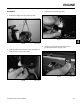
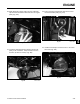
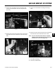
9. Remove the self tapping screws and washers that
secure the transmission to the front torque bracket
(Fig. 440).
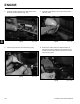
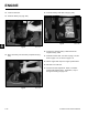
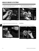
11. Remove the transmission mounting bracket (Fig.
442).
Fig 440 PICT-7233
Fig 442 PICT-7237
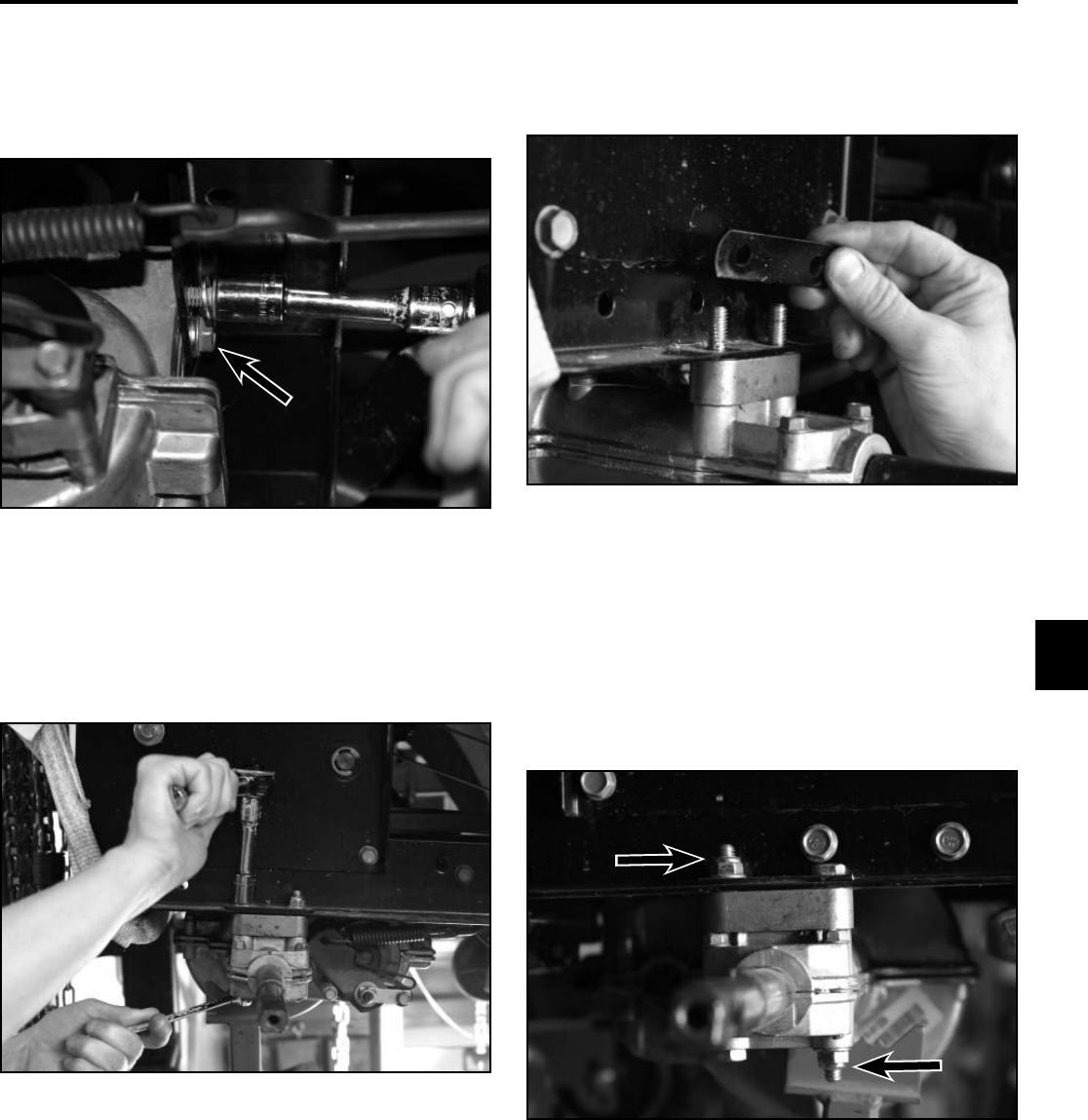
12. Remove the two hex bolts and lock nuts securing the
left hand side of the transmission to the frame.
Note: The rear hex bolt and lock nut are installed
opposite of the other three bolts retaining the
transmission to the frame (Fig. 443).
10. Remove the two hex bolts and lock nuts securing the
right hand side of the transmission to the frame (Fig.
441).
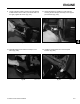
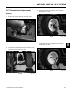
A. Front bolt, installed up
B. Rear bolt, installed down
Fig 443 PICT-7238
Fig 441 PICT-7236
A
A
B
B