
Service Manual

LX420, LX460
2006
3-18
Demystifi cation
G
uide
Circuits
Systems Indicator Monitor /
Hourmeter
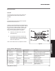
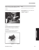
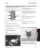
Purpose
Lights on the monitor panel are used to indicate the
position of the brake and PTO controls, as well as the
condition of the battery charging system. The LCD at
the center of the panel displays accumulated engine
hours and fl ashes when maintenance is due
(Figure 28).
How It Works
The Systems Indicator Monitor/Hourmeter is a solid
state device. Battery voltage from the A1 terminal of
the keyswitch powers the unit and runs the hourmeter.
An internal circuit monitors battery voltage and causes
the battery LED to light when battery voltage falls
below a specifi ed level. Additional sensing circuits
monitor the status of the brake and PTO switches.
When the brake is applied or the PTO is engaged,
contacts in the switches close, completing the sensing
circuit and lighting the appropriate LED.
Testing
Testing the Systems Indicator Monitor/Hourmeter
directly is not practical. If it is not functioning correctly,
test the inputs to the unit at the wiring harness
connector and replace the monitor if the inputs are
correct.
Note: The following tests are performed with the
engine off.
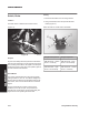
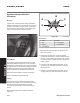
Wire Colors
A Green
B Black
C Red
D Orange/Black
E Orange
F Orange/White
G Orange/Black
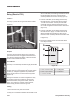
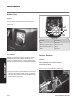
1. Disconnect the wiring harness connector from the
back of the monitor.
2. At the wiring harness plug, connect a voltmeter
positive lead to terminal “C” and the negative lead to
terminal “A” (Figure 29). With the key in the “normal”
or “Reverse Caution” position the meter should read
battery voltage.
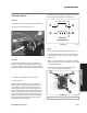
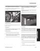
3. Connect an ohmmeter between terminals “F” and
“G” (Figure 29), the meter should show continuity
with the PTO off.
4. Connect an ohmmeter between terminals “D” and
“E” (Figure 29), the meter should show continuity
with the brake applied.
Figure
2
8
start sol
A
B
C
D
E
F
G
Figure
2
9
hourmeterplug