
Service Manual


CHASSIS
3-87LX Lawn Tractor Service Manual
3
Fig 333 PICT-7831
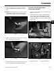
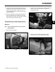
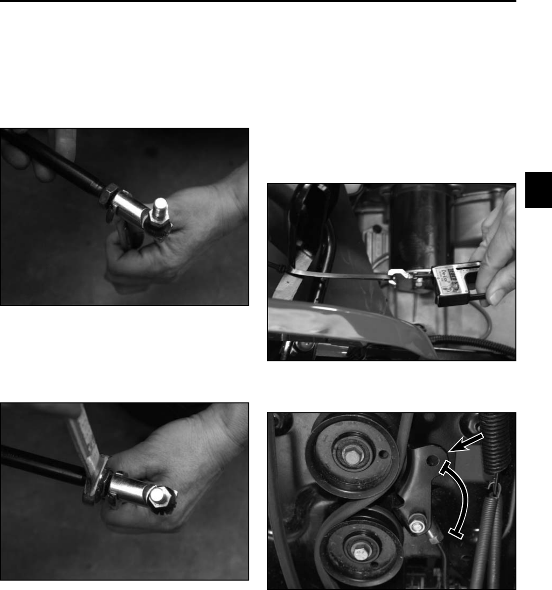
4. Tighten the jam nut to secure the position of the ball
joint to the steering rod (Fig. 333).
5. Install the ball joint to the steering arm and check the
toe-in as described in the measurement section.
Fig 332 PICT-7833
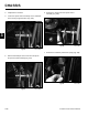
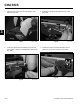
3. Rotate the ball joint one turn: clockwise to increase
toe-in; counterclockwise to decrease toe-in (Fig.
332).
IMPORTANT: If more than one turn is required to meet
specifi cations, alternate between the right and left
steering rods to maintain steering wheel alignment.
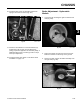
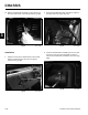
Fig 335 PICT-7673a
A. Double idler bracket B. 1-3/8” ravel distance
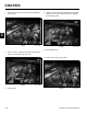
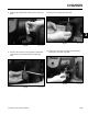
Fig 334 PICT-7670
1. Remove the mower deck. Refer to “46” Mower Deck
Removal” on page 7-69.
2. The Autodrive pedal is properly adjusted when the
hole found in the double idler bracket has approx-
imately 1-3/8” (3.5cm) of travel with 10 lbs. (4.5kg)
of pressure applied to the Autodrive pedal (Fig. 334
and Fig. 335).
Autodrive Pedal Adjustment -
Hydrostatic Models
A
A
B
B