
Service Manual
HYDROSTATIC DRIVE SYSTEM
6-9LX Lawn Tractor Service Manual
6
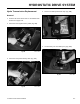
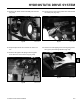
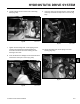
6. Loosely install a nut onto each of the 4 mounting
bolts (Fig. 518).
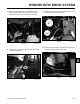
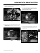
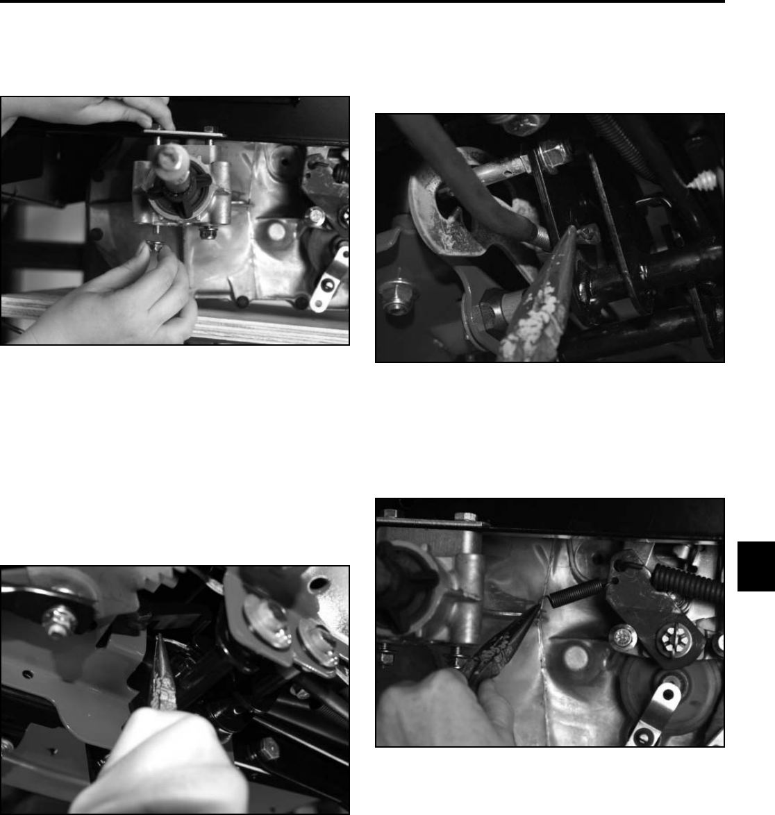
9. Insert the control rod trunnion into the control pedal
assembly and install a hairpin cotter to secure (Fig.
520).
Fig 518 PICT-7577
Fig 520 PICT-7533a
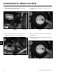
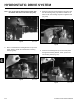
10. Attach the brake lever return spring to the axle
housing (Fig. 521).
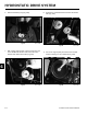
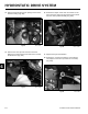
7. Tighten all 8 mounting bolts: 4 self tapping screws
securing the transmission mounting bracket to
the frame and 4 bolts and nuts securing the axle
housing to the frame.
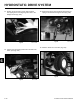
8. Insert the brake lever linkage rod into the brake lever
and install a cotter pin to secure (Fig. 519).
Fig 521 PICT-7557
Fig 519 PICT-7529