Consumer Products 2006 LX SERIES LAWN TRACTORS GT2000 SERIES GARDEN TRACTORS DEMYSTIFICATION GUIDE
About this manual We hope that you find this manual a valuable addition to your service shop. If you have comments or questions about this manual contact your Distributor Service Manager or us directly at the following assress: The Toro Company Consumer service department 8111 Lyndale Avenue South Bloomington, MN 55420-1196 The Toro company reserves the right to change product specifications or this manual without notice.
TABLE OF CONTENTS CHAPTER PAGE Table of contents . . . . . . . . . . . . . . . . . . . . . . . . . . . . . . . . . . . . . . . . . . . . . . . . . . . . . . . . . 1-1 Time Savers . . . . . . . . . . . . . . . . . . . . . . . . . . . . . . . . . . . . . . . . . . . . . . . . . . . . . . . . . . . . . 2-1 Glossary . . . . . . . . . . . . . . . . . . . . . . . . . . . . . . . . . . . . . . . . . . . . . . . . . . . . . . . . . . . . . . . . 3-1 LX420 / LX460 . . . . . . . . . . . . . . . . . . . . . . . . .
This page intentionally left blank 1-2 Demystification Glossary
TIME SAVERS Table of contents Using this manual . . . . . . . . . . . . . . . . . . . . . . . . . . . . . . . . . . . . . . . . . . . . . . . . . . . . . . . . . 2-2 Using a VOM . . . . . . . . . . . . . . . . . . . . . . . . . . . . . . . . . . . . . . . . . . . . . . . . . . . . . . . . . . . . 2-7 Troubleshooting . . . . . . . . . . . . . . . . . . . . . . . . . . . . . . . . . . . . . . . . . . . . . . . . . . . . . . . . . .
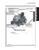
Using this Manual TIME SAVERS Solenoid, Starter The Glossary contains information on virtually every electrical part used on Toro riding products. Location The components are listed alphabetically by noun, followed The starter solenoid is located under the rear fender by any adjectives. If you have assembly to the right of the battery (Figure 8). trouble finding a component, use the Table of Contents at the front of the Glossary section.
TIME SAVERS Using this Manual Each product series has its own 2006 section including: LX420, LX460 - Info List - Wiring Diagrams - Circuit Diagrams Information List Image helps you quickly identify product sections. Each product section has its own "Table of Contents" to keep things simple. The "Info List" is the first page of each product section. LX420 Information List (2006) LX460 Information List (2006) Wiring Diagram. . . . . . . . . . . . . . . . . . . . . . . . . . . . . .
TIME SAVERS Using this Manual LX420, LX460 2006 Wiring Diagram Each product section includes the original wiring diagram.
TIME SAVERS LX420, LX460 Wiring Diagram WIRE COLOR CODES BN BU GY W PUR R BROWN BLUE GRAY WHITE PURPLE RED OR/BK OR/W Y/W Y/BK R/W R/BK PINK BLACK YELLOW TAN GREEN ORANGE ORNGE BLACK ORNGE WHITE YELLOW WHITE YELLOW BLACK RED WHITE RED BLACK R 20A B+ R R PTO SWITCH R PTO SWITCH IS SHOWN WITH PTO OFF Wiring Diagram FUSE R/W PK BK Y T GN OR - + STARTER START Y/BK Y OR/BK OR/W SPARK PLUG SOLENOID Y R/W R IGNITION MODULE The wiring diagram Y MAG closely represents the R/W REG wiring
Using this Manual TIME SAVERS Each circuit is shown individually. Components LX500,GT2100 not essential for circuit function are not shown. GT2200, GT2300 2006 Components with internal circuitry are enclosed with a dashed line. Solid lines indicate wires that carry current.
TIME SAVERS 1 Demystification Glossary Using a VOM 2 Checking Voltage Checking Resistance 2-7
TIME SAVERS Using a VOM 3 What about checking current? 2-8 Demystification Glossary
TIME SAVERS Sample Problem: GT2100 electric clutch will not engage Troubleshooting Dashed lines do not carry current R TIP: DON'T DISCONNECT ANY WIRES! When checking for voltage you need only touch the terminals. (disconnect components when checking resistance.) SPARK PLUG Brake Switch (Brake Off) Seat Switch (Operator On) Fuel Solenoid (Energized) IGNITION MODULES Y Y/W SPARK PLUG R Bu GN Bu Y GN Rw G M B A1 1.
Troubleshooting TIME SAVERS Sample Problem: This GT tractor won’t turn over. The customer parked it in the garage and turned it off. When he tried to start it a week later, he heard one click. After that, nothing would happen when he turned the key. We know it’s a short because we found the 20 amp fuse blown. IGNITION SWITCH Step 1. Interview the customer. Any information we get will help isolate the problem.
TIME SAVERS Troubleshooting Step 2. Isolate the suspect area. Notice what we did to the wiring diagram below. WIRE COLOR CODES BN BU GY W PUR R BROWN BLUE GRAY WHITE PURPLE RED PK BK Y T GN OR PINK BLACK YELLOW TAN GREEN ORANGE OR/BK OR/W Y/W Y/BK R/W R/BK ORANGE BLACK ORANGE WHITE YELLOW WHITE YELLOW BLACK RED WHITE RED BLACK If the short was between the battery and the 20 amp fuse, we would have melted these wires.
Troubleshooting TIME SAVERS Step 3. Break the suspect area down into “mini-circuits”. Do this by unplugging unswitched circuits and by opening all Switches. IGNITION SWITCH OFF RUN 1 RUN 2 START Open the ignition switch by turning it “off”. L G M A1 B A1 AND L A2 B A1 B S A1 G M GN GN Y S B A1 A2 HEADLIGHT HARNESS GN BU GN R OR R/W R PUR R/W R Separate the connector for the lights since this is an unswitched circuit.
TIME SAVERS Troubleshooting WIRE COLOR CODES BN BU GY W PUR R BROWN BLUE GRAY WHITE PURPLE RED PK BK Y T GN OR PINK BLACK YELLOW TAN GREEN ORANGE OR/BK OR/W Y/W Y/BK R/W R/BK FUSE R/W R 20A R ORANGE BLACK ORANGE WHITE YELLOW WHITE YELLOW BLACK RED WHITE RED BLACK Remove the connector B+ R + from the PTO switch to open both suspect circuits.
Troubleshooting TIME SAVERS When the ignition switch is turned to “normal”, the 20 amp fuse doesn’t blow. This means the red wires are OK. Step 4. Power up the mini-circuits one at a time, beginning with the one closest to the battery. IGNITION SWITCH OFF RUN 1 RUN 2 START Next, turn the ignition switch to “start”. This powers up the orange, HEADLIGHT HARNESS orange/black, and orange/white wires. The fuse doesn’t blow so these wires are OK.
TIME SAVERS Troubleshooting WIRE COLOR CODES BN BU GY W PUR R BROWN BLUE GRAY WHITE PURPLE RED PK BK Y T GN OR PINK BLACK YELLOW TAN GREEN ORANGE OR/BK ORANGE BLACK Install a new fuse. OR/W20 amp ORANGE WHITE Y/W up” YELLOW WHITE This “powers the red/white Y/BK YELLOW BLACK wire to theR/W ignition The REDswitch. WHITE R/BK RED BLACK fuse doesn’t blow, so this wire is OK.
Troubleshooting TIME SAVERS IGNITION SWITCH OFF RUN 1 RUN 2 START Leave the ignition switch in the “normal” position. L G M A1 B A1 AND L A2 B A1 B S A1 G M GN GN Y S B A1 A2 HEADLIGHT HARNESS GN BU GN R OR R/W R PUR R/W R Reconnect the light circuit, the fuse doesn’t blow so this circuit is OK. BRAKE SWITCH GN BRAKE SWITCH IS SHOWN WITH BRAKE APPLIED Y Separate the plug at the electric clutch and check the blue/white GN wire for continuity to ground. We find there is continuity.
TIME SAVERS Troobleshooting WIRE COLOR CODES BN BU GY W PUR R BROWN BLUE GRAY WHITE PURPLE RED PK BK Y T GN OR PINK BLACK YELLOW TAN GREEN ORANGE OR/BK OR/W Y/W Y/BK R/W R/BK ORANGE BLACK ORANGE WHITE YELLOW WHITE YELLOW BLACK RED WHITE RED BLACK FUSE R/W R 20A R PTO SWITCH PTO SWITCH IS SHOWN WITH PTO OFF BU/W Y/W W/BK OR/BK B+ R Close the PTO switch by pulling R it to the “on” position.
This page intentionally left blank 2-18 Demystification Glossary
GLOSSARY Table Of Contents DESCRIPTION Clutch, Electric PTO . . . . . . . . . . . . . . . . . . . . . . . . . . . . . . . . . . . . . . . . . . . . . . . . . . . . . . . 3-3 Fuse . . . . . . . . . . . . . . . . . . . . . . . . . . . . . . . . . . . . . . . . . . . . . . . . . . . . . . . . . . . . . . . . . . . 3-4 RMC Module . . . . . . . . . . . . . . . . . . . . . . . . . . . . . . . . . . . . . . . . . . . . . . . . . . . . . . . . . . . . 3-5 Relay (Electric PTO) . . .. . . . . . . . . . . . . . . . .
This page intentionally left blank 3-2 Demystifiction Glossary
GLOSSARY Clutch, Electric PTO 4. Connect the meter lead wires to the wires in the clutch connector (Figure 1). Purpose This clutch electrically controls the engagement and disengagement of the Power Take Off (PTO) pulley. How It Works The PTO clutch is composed of three major components; the field, the clutch plate, and the friction plate. The clutch plate always turns with the engine. The field is a coil of wire on an iron core, which becomes an electromagnet when power is applied.
GLOSSARY Fuse Location The 20 amp fuse is located at the right side of the fuel tank. It is wired in series between the battery positive terminal and the “B” terminal of the ignition switch (Figure 3). Figure 2 3-7 Clutch Burnishing Procedure The clutch should be burnished as part of the pre delivery service, or whenever a new clutch is installed. Burnishing polishes the clutch plate, allowing for smooth clutch engagement. With a PTO driven attachment installed (i.e.
GLOSSARY Testing A blade type fuse may be checked visually. If the loop (A) is open, the fuse is blown. If in doubt, the fuse may also be tested with an ohmmeter (Figure 4). Figure 4 fuse20a RMC Module This interlock feature is provided to prevent unintentional engine-powered attachment operation in reverse.
GLOSSARY Location On units equiped with electric PTO clutch The RMC module is located on the back of the instrument panel in the same housing as the keyswitch (Figure 5). The reverse switch is connected in series between module and ground. When the Module is not activated (indicator light off) the switch is internally connected to the E-PTO terminal. If the shift lever is placed in reverse, the relay coil is connected to ground through the RMC module and reverse switch, energizing the relay.
GLOSSARY Testing the RMC system – Manual PTO - keyswitch in “Reverse Caution” Unactivated (Indicator light off) Testing the RMC system – Electric PTO - keyswitch in “Reverse Caution” Unactivated (Indicator light off) 1. Start the engine; place the keyswitch in the reverse caution position. 1. Start the engine; place the keyswitch in the reverse caution position. 2. With the seat occupied, place the PTO lever in the “on” position. 2. With the seat occupied, pull the PTO switch to the “on” position. 3.
GLOSSARY Testing the RMC module It is not practical to test the RMC module directly. If the RMC system is not functioning as described above, it will be necessary to test the inputs to, and outputs from, the module. If the inputs are correct but the outputs are not, replace the module. Connect an ohmmeter between the E-PTO terminal at the module (yellow/black wire) and ground.
GLOSSARY Manual PTO Clutch Symptom: The engine does not shut down when shifting into reverse when the reverse caution mode is not activated. OR The engine does not shut down when the operator leaves the seat with the PTO on. Connect an ohmmeter between the magneto terminal (yellow/black wire) at the module and ground.
GLOSSARY Relay (Electric PTO) with a multimeter (ohms setting). Resistance should be approximately 105 ohms. There should be continuity between terminals A and E (Figure 10). Location The relay is part of the wiring harness and is located behind the fuel tank near the PTO connector (Figure 9). 3. Connect multimeter (ohms setting) leads to relay terminals E and C. Ground terminal B and apply +12 VDC to terminal D.
GLOSSARY Solenoid, Starter The ignition switch is protected because only a small amount of current is needed to activate the coil. Location The starter solenoid is located under the rear fender behind the battery. Remove the battery and battery tray to access the solenoid (Figure 11). C D A B Solenoid (not energized) Figure 12 start sol Testing 1. Disconnect the solenoid from the wiring harness. Figure 11 solloc Purpose How It Works 3. Apply +12 VDC to terminal “a” and ground mounting tab “B”.
GLOSSARY Switch, Brake Testing 1. Disconnect the switch from the wiring harness. Location The brake switch is attached to the tractor frame, under the fuel tank, near the base of the brake lever (Figure 14). Figure 14 tbrakesw Purpose GLOSSARY As part of the safety interlock system the brake switch has two sets of terminals; one pair prevents the engine from cranking if the brake is not applied. The other pair causes the engine to shut down if the operator gets off the seat with the brake released.
GLOSSARY Switch, Parking Brake (Manual PTO) Testing 1. Disconnect the switch from the wiring harness. Location The parking brake switch is located under the fuel tank near the locking lever (Figure 16). Figure 16 2. Use a ohmmeter to test continuity between the terminals (figure 17). Plunger out – no continuity Plunger in - continuity prkbrksw Purpose The parking brake switch is part of the safety interlock system.
GLOSSARY Switch, Key Purpose This component provides the proper switching for the starter, ignition, accessories, and safety circuits (Figure 18). L G A1 A2 S M B Figure 19 Figure 18 Condition Off G+M+A1 Reverse Caution (Run 1) B+A 1 & L+A 2 Normal Mowing (Run 2) B+A 1 Start B+S+A 1 keysw How It Works GLOSSARY Position swign Detents inside the switch give it 4 positions: STOP, REVERSE CAUTION, NORMAL MOWING, and START.
GLOSSARY Units equipped with hydrostatic transmissions Switch, Seat (Electric PTO Clutch) The reverse switch is located on the right side of the transmission near the brake (Figure 21). Purpose Shuts the engine down if the operator gets off the seat with the brake not applied. Disengages the PTO Clutch if the operator gets out of the seat with the PTO engaged. Figure 21 swhydrorev Purpose (All units) Provides ground signal to RMC module when the shift lever is in reverse.
GLOSSARY Switch, Seat (Manual PTO Clutch) Switch, PTO (Electric PTO) Purpose Purpose To shut the engine down if the operator gets off the seat while the engine is running with the PTO engaged or the brake released. The PTO switch is used to engage the electric clutch (Figure 24). Figure 24 Figure 23 tseatsw GLOSSARY How It Works The seat switch consists of a pair of normally closed contacts which open when the operator is on the seat (Figure 23).
2006 LX420, LX460 the ignition switch and the electric clutch. Pulling the switch to the on position closes these contacts providing voltage to the electric clutch. Purpose Part of the safety interlock system: 1. Prevents the engine from cranking if the PTO lever is in the engaged position. 2. Shuts the engine down if the operator gets off the seat with the PTO lever in the engaged position, or the shift lever is placed in the reverse position without activating the reverse caution mode.
LX420, LX460 2006 Systems Indicator Monitor / Hourmeter B Purpose Lights on the monitor panel are used to indicate the position of the brake and PTO controls, as well as the condition of the battery charging system. The LCD at the center of the panel displays accumulated engine hours and flashes when maintenance is due (Figure 28). A C G D F E Figure 29 hourmeterplug Wire Colors A Green B Black C Red D Orange/Black E Orange F Orange/White G Orange/Black 1.
2006 LX420, LX460 Information List LX420 Information List (2006) LX460 Information List (2006) Wiring Diagram. . . . . . . . . . . . . . . . . . . . . . . . . . . . . . . 4-2 Circuit Diagrams Starter Motor Circuit . . . . . . . . . . . . . . . . . . . . . . 4-4 Spark Circuits . . . . . . . . . . . . . . . . . . . . . . . . . . . 4-5 Reverse Operating System . . . . . . . . . . . . . . . .
LX420, LX460 2006 Wiring Diagram IGNITION SWITCH L G M GN GN Y S B A1 A2 R W OFF RUN 1 RUN 2 START G M A1 B A1 AND L A2 B A1 B S A1 Wiring Diagram HEADLIGHT HARNESS GN BU GN R OR R/W R/W BRAKE SWITCH BRAKE SWITCH IS SHOWN WITH BRAKE APPLIED Y OR Y/BK Y OR/BK OR/BK Y Y R/W R/W R Y/BK BRAKE + OR BRAKE OR/BK PTO OR/W PTO + OR/BK OR/W N/C + 12V GND R GN SYSTEMS INDICATOR MONITOR / HOUR METER R W Y/W GN PARK SWITCH GND 4-2 PARK SWITCH IS SHOWN PARK BRAKE ON D
2006 LX420, LX460 Wiring Diagram WIRE COLOR CODES BN BU GY W PUR R BROWN BLUE GRAY WHITE PURPLE RED PK BK Y T GN OR PINK BLACK YELLOW TAN GREEN ORANGE OR/BK OR/W Y/W Y/BK R/W R/BK ORANGE BLACK ORANGE WHITE YELLOW WHITE YELLOW BLACK RED WHITE RED BLACK Wiring Diagram FUSE R/W R B+ R 20A - + R STARTER PTO SWITCH R PTO SWITCH IS SHOWN WITH PTO OFF START Y/BK Y OR/BK OR/W SPARK PLUG SOLENOID Y R/W Y MAG R/W REG IGNITION MODULE AC AC AFTERFIRE SOLENOID R R Y/BK Y/BK OR/W Y/BK
LX420, LX460 2006 Starter Motor Circuit (ignition switch in “start”) R R R OR/W Brake Switch (Brake Applied) OR R B Battery Fuse (20 Amp) PTO Switch (PTO Off) OR/BK Starter Motor (Energized) OR/W S R/W R Starter Solenoid (Energized) R A1 Ignition Switch (In Start) R Fuel Solenoid (Energized) R BU GN Headlight Harness (Headlights on) Circuits WIRE COLOR CODES BN BU GY W PUR R 4-4 BROWN BLUE GRAY WHITE PURPLE RED PK BK Y T GN OR PINK BLACK YELLOW TAN GREEN ORANGE OR/BK OR/W Y/W
2006 LX420, LX460 Spark Circuit (ignition switch in “start”) Y GN G M Dashed lines do not carry current Ignition Switch (In Start) SPARK PLUG Brake Switch (Brake Applied) Seat Switch (Operator On) GN IGNITION MODULE Y Y/W PTO Switch (PTO Off) Y/B Y WIRE COLOR CODES Demystification Guide BROWN BLUE GRAY WHITE PURPLE RED PK BK Y T GN OR PINK BLACK YELLOW TAN GREEN ORANGE OR/BK OR/W Y/W Y/BK R/W R/BK ORANGE BLACK ORANGE WHITE YELLOW WHITE YELLOW BLACK RED WHITE RED BLACK 4-5 Circuits BN
LX420, LX460 2006 Spark Circuit (ignition switch in “Normal”, PTO “on”) Dashed lines do not carry current SPARK PLUG Brake Switch (Brake Off) Y/BK Seat Switch (Operator On) GN Y IGNITION MODULE Y PTO Switch (PTO On) Y/BK Y/BK Y GN R/W G M B A1 Y R GN Ground GN Park Switch (Brake Off) A1 Power Rev Sw R/BK RMC Module Reverse Switch (In Forward) R/W Battery Y/W Park Sw R Ignition Switch (In Normal) R PB Bypass Magneto Y/BK Fuse (20 Amp) R Fuel Solenoid (Energized) R BU GN
2006 LX420, LX460 Spark Circuit (ignition switch in “Normal”, operator “off”, brake “on”, PTO “off”) SPARK PLUG PTO Switch (PTO Off) Y/BK Seat Switch (Operator Off) GN Y IGNITION MODULE Y Brake Switch (Brake On) Y/BK Y Y/BK R Y GN R/W G M B A1 Magneto Y/BK A1 Power Battery GN Ground GN Park Switch (Brake Off) Y/W Park Sw R Rev Sw Ignition Switch (In Normal) R PB Bypass R/BK RMC Module Reverse Switch (In Forward) R/W R Fuse (20 Amp) Fuel Solenoid (Energized) R BU GN R BU
LX420, LX460 2006 Spark Circuit (ignition switch in “Normal”, operator “off”, brake “on”, PTO “on”) SPARK PLUG Brake Switch (Brake On) GN IGNITION MODULE Y Y Y/BK Seat Switch (Operator Off) PTO Switch (PTO On) Y/BK Y/BK Y GN R/W G M B A1 Y Magneto Y/BK R GN Ground GN Park Switch (Brake Off) A1 Power Rev Sw R/BK RMC Module Reverse Switch (In Forward) R/W Battery Y/W Park Sw R Ignition Switch (In Normal) R PB Bypass Fuse (20 Amp) R Fuel Solenoid (Energized) R BU GN R C
2006 LX420, LX460 Reverse Operating System (ignition switch in “Normal”, PTO “on”, transmission in “reverse”) SPARK PLUG Brake Switch (Brake Off) Y/BK Seat Switch (Operator On) GN IGNITION MODULE Y Y PTO Switch (PTO On) Y/BK Y Y/BK R Y GN R/W G M B A1 Magneto Y/BK Battery GN Ground GN Park Switch (Brake Off) A1 Power Y/W Park Sw R Rev Sw Ignition Switch (In Normal) R PB Bypass R/BK RMC Module Reverse Switch (In Reverse) R/W R Fuel Solenoid (Energized) Fuse (20 Amp) R BU GN
LX420, LX460 2006 Reverse Oprerating System (ignition switch in “Reverse Caution”, PTO “on”) Dashed lines do not carry current SPARK PLUG Brake Switch (Brake Off) Y/BK Seat Switch (Operator On) GN Y IGNITION MODULE Y PTO Switch (PTO On) Y/BK Y Y/BK PUR R GN G M PB Bypass GN Ground GN Magneto Y/BK A2 Power L A2 B A1 Y/W Park Sw Rev Sw A1 Power R/BK RMC Module Y Reverse Switch (In Forward) PUR R/W Park Switch (Brake Off) R Ignition Switch (In Caution) R R R/W Battery F
2006 LX420, LX460 Reverse Operating System (ignition switch in “Reverse Caution”, transmission in “reverse”, PTO “on”) Dashed lines do not carry current SPARK PLUG Brake Switch (Brake Off) Y/BK Seat Switch (Operator On) GN Y IGNITION MODULE Y PTO Switch (PTO On) Y/BK Y Y/BK PUR A2 Power R GN G M PB Bypass GN Ground GN Magneto Y/BK Y/W Park Sw Rev Sw A1 Power R/BK RMC Module Y Reverse Switch (In Reverse) PUR R/W L A2 B A1 Park Switch (Brake Off) R Ignition Switch (In Cautio
LX420, LX460 2006 Reverse Operating System (ignition switch in “Reverse Caution”, RMC “activated”, transmission in “reverse”, PTO “on”) Dashed lines do not carry current SPARK PLUG Brake Switch (Brake Off) Y/BK Seat Switch (Operator On) GN Y IGNITION MODULE Y PTO Switch (PTO On) Y/BK Y Y/BK PUR R GN G M PB Bypass GN Ground GN Magneto Y/BK A2 Power L A2 B A1 Y/W Park Sw Rev Sw A1 Power R/BK RMC Module Y Reverse Switch (In Reverse) PUR R/W Park Switch (Brake Off) R Ignitio
2006 LX500,GT2100 GT2200, GT2300 Information List LX500 Information List (2006) GT2100 Information List (2006) GT2100 Information List (2006) GT2100 Information List (2006) Wiring Diagram. . . . . . . . . . . . . . . . . . . . . . . . . . . . . . . 5-2 Circuit Diagrams Starter Motor Circuit . . . . . . . . . . . . . . . . . . . . . . 5-4 Spark Circuits . . . . . . . . . . . . . . . . . . . . . . . . . . . 5-5 PTO Circuits . . . . . . . . . . . . . . . . . . . . . . . . . . . .
LX500, GT2100 GT2200, GT2300 2006 Wiring Diagram IGNITION SWITCH Wiring Diagram OFF RUN 1 RUN 2 START L G M A1 B A1 AND L A2 B A1 B S A1 G M GN GN Y S B A1 A2 HEADLIGHT HARNESS GN BU GN R OR R/W R PUR R/W R BRAKE SWITCH GN BRAKE SWITCH IS SHOWN WITH BRAKE APPLIED Y OR Y/W OR/BK GN Y BU/W BU/W PTO CLUTCH R/W R W Relay W W/BK R 3 GN 1 4 5 2 Y/BK Y/BK W/BK BRAKE + OR BRAKE OR/BK OR/BK PTO OR/W OR/W PTO + OR/BK R PUR N/C + 12V GND R GN GN SYSTEMS INDICATOR
2006 LX500, GT2100 GT2200, GT2300 Wiring Diagram WIRE COLOR CODES BROWN BLUE GRAY WHITE PURPLE RED PK BK Y T GN OR PINK BLACK YELLOW TAN GREEN ORANGE OR/BK OR/W Y/W Y/BK R/W R/BK ORANGE BLACK ORANGE WHITE YELLOW WHITE YELLOW BLACK RED WHITE RED BLACK Wiring Diagram BN BU GY W PUR R FUSE R/W R B+ R 20A - + R R PTO SWITCH STARTER R PTO SWITCH IS SHOWN WITH PTO OFF BU/W Y/W OR/BK W/BK START SPARK PLUG R Y/BK OR/W OR/BK OR/W Y MAG R/W REG SPARK PLUG IGNITION MODULES AC SOLENOID
LX500, GT2100 GT2200, GT2300 2006 Starter Motor Circuit (ignition switch in “start”) R R R OR/W PTO Switch (PTO Off) Brake Switch (Brake Applied) OR R B Battery Fuse (20 Amp) Starter Motor (Energized) OR/W S R/W R OR/BK Starter Solenoid (Energized) R A1 Ignition Switch (In Start) R Fuel Solenoid (Energized) R BU GN Headlight Harness (Headlights on) Circuits WIRE COLOR CODES BN BU GY W PUR R 5-4 BROWN BLUE GRAY WHITE PURPLE RED PK BK Y T GN OR PINK BLACK YELLOW TAN GREEN ORANGE
2006 LX500,GT2100 GT2200, GT2300 Spark Circuit (ignition switch in “start”) Y GN G M Dashed lines do not carry current Ignition Switch (In Start) Seat Switch (Operator On) GN SPARK PLUG Brake Switch (Brake Applied) Y/W SPARK PLUG IGNITION MODULES Y WIRE COLOR CODES Demystification Guide BROWN BLUE GRAY WHITE PURPLE RED PK BK Y T GN OR PINK BLACK YELLOW TAN GREEN ORANGE OR/BK OR/W Y/W Y/BK R/W R/BK ORANGE BLACK ORANGE WHITE YELLOW WHITE YELLOW BLACK RED WHITE RED BLACK 5-5 Circuits BN BU
LX500, GT2100 GT2200, GT2300 2006 Spark Circuit (ignition switch in “Normal”, PTO “on”) Dashed lines do not carry current R SPARK PLUG Brake Switch (Brake Off) Seat Switch (Operator On) Fuel Solenoid (Energized) IGNITION MODULES Y Y/W SPARK PLUG R BU Y GN GN R BU Headlight Harness (Headlights on) Y Seat Switch Ground R Y GN R/W G M B A1 Y/BK R R Battery E-PTO Rev Sw RMC Module Ignition Switch (In Normal) PTO Switch (PTO On) R/W R Fuse (20 Amp) Y/BK BU/W W/BK PTO Clutch (Eng
2006 LX500,GT2100 GT2200, GT2300 PTO Circuit (ignition switch in “Normal”, operator “off”, brake “on”) Dashed lines do not carry current R Seat Switch (Operator Off) Fuel Solenoid (Energized) IGNITION MODULES Y Y/W SPARK PLUG SPARK PLUG Brake Switch (Brake On) R BU Y GN GN R BU Headlight Harness (Headlights on) Y Seat Switch Ground R Y GN R/W G M B A1 Y/BK R R PTO Switch (PTO On) R/W BU/W Battery Fuse (20 Amp) E-PTO Rev Sw RMC Module Ignition Switch (In Normal) Y/BK PTO C
LX500, GT2100 GT2200, GT2300 2006 PTO Circuit (ignition switch in “Normal”, operator “off”, PTO “on”) Dashed lines do not carry current R Seat Switch (Operator Off) Fuel Solenoid (Energized) IGNITION MODULES Y Y/W SPARK PLUG SPARK PLUG Brake Switch (Brake Off) R BU Y GN GN R BU Headlight Harness (Headlights on) Y Seat Switch Ground R Y GN R/W G M B A1 Y/BK R Rev Sw R/BK Reverse Switch (In Forward) PTO Switch (PTO On) R/W R Battery E-PTO RMC Module Ignition Switch (In Normal)
2006 LX500,GT2100 GT2200, GT2300 Reverse Operating System (ignition switch in “Reverse Caution”, PTO “on”, transmission in “foward”) Dashed lines do not carry current R SPARK PLUG Brake Switch (Brake Off) Seat Switch (Operator On) Fuel Solenoid (Energized) IGNITION MODULES Y Y/W SPARK PLUG R BU Y GN GN R BU Headlight Harness (Headlights on) Y GN G M L A2 PUR GN R/W R Y B PUR R Y/BK A1 Ignition Switch (In Reverse Caution) R Battery A1 Power Ground GN A2 Power Rev Sw E-PTO R/
LX500, GT2100 GT2200, GT2300 2006 Reverse Operating System (ignition switch in “Normal”, PTO “on”, transmission in “reverse”) Dashed lines do not carry current R SPARK PLUG Brake Switch (Brake Off) Seat Switch (Operator On) Y Y/W SPARK PLUG Fuel Solenoid (Energized) IGNITION MODULES R BU Y GN GN R BU Headlight Harness (Headlights on) Y R Y GN R/W G M B A1 Y/BK R PTO Switch (PTO On) R/W R Battery Ground Fuse (20 Amp) Y/BK BU/W W/BK PTO Clutch (Released) GN A1 Power E-PTO Rev
2006 LX500,GT2100 GT2200, GT2300 PTO Circuit (ignition switch in “Reverse Caution”, PTO “on”, transmission in “reverse”) Dashed lines do not carry current R SPARK PLUG Brake Switch (Brake Off) Seat Switch (Operator On) Fuel Solenoid (Energized) IGNITION MODULES Y Y/W SPARK PLUG R BU Y GN GN R BU Headlight Harness (Headlights on) Y Seat Switch Ground GN G M L A2 PUR GN R/W R Y B PUR R Y/BK A1 Ignition Switch (In Reverse Caution) R PTO Switch (PTO On) R/W Fuse (20 Amp) A2 Power
LX500, GT2100 GT2200, GT2300 2006 PTO Circuit (ignition switch in “Reverse Caution”, RMC “activated”, PTO “on”, transmission in “reverse”) Dashed lines do not carry current R SPARK PLUG Brake Switch (Brake Off) Seat Switch (Operator On) Fuel Solenoid (Energized) IGNITION MODULES Y Y/W SPARK PLUG R BU Y GN GN R BU Headlight Harness (Headlights on) Y GN G M L A2 PUR GN R/W R Y B PUR R Y/BK A1 Ignition Switch (In Reverse Caution) R PTO Switch (PTO On) R/W Fuse (20 Amp) A1 Power
2006 LX Series Lawn Tractors GT2000 Series Garden Tractors Demystification Guide Form No.