
Service Manual


GLOSSARY
3-8
Demystifi ction
Glossary
GLOSSARY
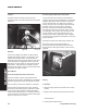
Testing the RMC module
It is not practical to test the RMC module directly. If the
RMC system is not functioning as described above,
it will be necessary to test the inputs to, and outputs
from, the module. If the inputs are correct but the
outputs are not, replace the module.
Note: Be sure the battery is fully charged before
testing.
Electric PTO Clutch
Symptom
:
The electric clutch does not disengage when shifting
into reverse with the reverse caution mode not
activated.
OR
The electric clutch does not disengage when the
operator leaves the seat with the PTO on.
Connect an ohmmeter between the E-PTO terminal at
the module (yellow/black wire) and ground. With the
key in the “ON” or “Reverse Caution” position, PTO
switch on, and the seat occupied the meter should
show continuity when the shift lever is placed in
reverse, or the operator gets out of the seat.
a) Continuity: the module is OK, check the relay
or associated wiring.
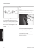
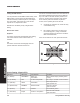
b) No continuity: Remove the connector from
the module (Figure 7). Using a multimeter
check the electrical circuits for the conditions
listed in the table below.
If the circuit conditions are met, replace the module.
Terminal
Wire Color
Connected to
Condition
A - (E-PTO)
Yellow/Black
Relay coil
PTO switch
RMC module output, provides ground
to relay
B - (A1 Power)
Red
A1 term of keyswitch
B+ w/ key in “normal” or “Rev. Caution”
C - (Seat Sw)
Yellow
Seat switch
Ground operator on
Open operator off
D - (Reverse Sw)
Red/Black
Reverse switch
Ground in reverse
Open in forward
E - (Ground)
Green
Chassis
Connected to ground
F - (A2 Power)
Purple
A2 Term. of keyswitch
Ground in Rev. Caution
Open otherwise
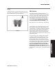
Circuit Testing - Electric PTO
DA
B
C
E
F
Figure
7
RMCPlugElec1