
Service Manual

2006 LX420, LX460
D
emystifi cation Guide
3-17
Circuits
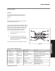
the ignition switch and the electric clutch. Pulling
the switch to the on position closes these contacts
providing voltage to the electric clutch.
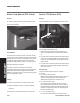
Testing
1. Remove the PTO switch from the tractor.
2. Connect an ohmmeter across each pair of terminals
and check for continuity with the switch in the “OFF”
and “ON” positions.
3. Replace the switch if the results do not correspond
to the description given above.
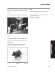
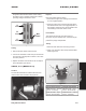
Switch, PTO (Manual PTO)
Location
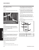
The manual PTO Switch is located under the hood
near the base of the actuation rod (Figure 26).
Purpose
Part of the safety interlock system:
1. Prevents the engine from cranking if the PTO lever
is in the engaged position.
2. Shuts the engine down if the operator gets off the
seat with the PTO lever in the engaged position, or
the shift lever is placed in the reverse position with-
out activating the reverse caution mode.
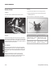
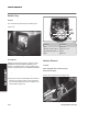
How It Works
This double pole plunger type switch has four
terminals, one pair normally open, and the other pair
normally closed. When the PTO lever is in the off
position the plunger is depressed.
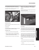
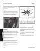
Testing
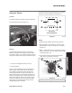
1. Disconnect the switch from the wiring harness.
2. Using a an ohmmeter, follow the procedures listed
below (Figure 27):
Note: Terminals on actual switch not labeled.
Plunger Not Depressed
Plunger Depressed
A&B Terminals – Closed
Circuit – Continuity
A&B Terminals – Open
Circuit – No Continuity
C&D Terminals – Open
Circuit – No Continuity
C&D Terminals – Closed
Circuit – Continuity
A
Com
Not
Used
B
Com
C
Com
Figure
2
5
swelecpto
Figure
2
6
tptosw
Figure
2
7
manptoterm