Operator’s Manual Form No. 3354-969 Rev. G Register your product at www.Toro.com LX420 & LX460 Lawn Tractors Model No. 13AX60RG744 Model No.
California Proposition 65 Warning: WARNING: Engine exhaust, some of its constituents, and certain vehicle components contain or emit chemicals known to the State of California to cause cancer and birth defects or other reproductive harm.
SECTION 1: IMPORTANT SAFE OPERATION PRACTICES WARNING: This symbol points out important safety instructions which, if not followed, could endanger the personal safety and/or property of yourself and others. Read and follow all instructions in this manual before attempting to operate this machine. Failure to comply with these instructions may result in personal injury. When you see this symbol–heed its warning.
DO: 21. Never leave a running machine unattended. Always turn off blade(s), place transmission in neutral, set parking brake, stop engine and remove key before dismounting. 22. Use extra care when loading or unloading the machine into a trailer or truck. This unit should not be driven up or down ramp(s), because the unit could tip over, causing serious personal injury. The unit must be pushed manually on ramp(s) to load or unload properly. 23. Muffler and engine become hot and can cause a burn.
CHILDREN 5. Travel slowly and allow extra distance to stop. 6. On slopes, the weight of the towed equipment may cause loss of traction and loss of control. 7. Do not shift to neutral and coast downhill. 1. Tragic accidents can occur if the operator is not alert to the presence of children. Children are often attracted to the machine and the mowing activity. They do not understand the dangers. Never assume that children will remain where you last saw them. a.
8. Never tamper with the safety interlock system or other safety devices. Check their proper operation before each use. 9. After striking a foreign object, stop the engine and remove the ignition key to prevent unintended starting. Thoroughly inspect the machine for any damage. Repair the damage before starting and operating. 10. Never attempt to make adjustments or repairs to the machine while the engine is running. 11.
SECTION 2: SAFETY AND INSTRUCTIONAL LABELS Safety and instructional abels found on your lawn tractor are illustrated below (3/4 actual size). Always follow their instructions and heed their warnings. If you discover a safety label is scratched, damaged or missing, order a replacement immediately. TO START DANGER • • • • 1. 2. 3. 4. ROTATING BLADES CAUSE SERIOUS INJURY OR DEATH DO NOT MOW WHEN CHILDREN OR OTHERS ARE AROUND NEVER CARRY CHILDREN EVEN WITH BLADE(S) OFF.
TO REDUCE THE RISK OF INJURY, DO NOT OPERATE UNLESS DISCHARGE COVER OR GRASS CATCHER IS IN ITS PROPER PLACE. IF DAMAGED, REPLACE IMMEDIATELY. Part No. 112-1274 Part No. 112-1266 Part No. 112-1271 LX420 Part No. 112-1270 LX460 Part No. 112-1267 DANGER/POISON SHIELD EYES. EXPLOSIVE GASES CAN CAUSE BLINDNESS OR INJURY. Part No. 112-1269 PROTÉGER LES. YEUX. LES GAZ EXPLOSIFS. PEUVENT BLESSER OU RENDRE AVEUGLE. SULFURIC ACID FLUSH EYES IMMEDIATELY WITH CAN CAUSE BLINDNESS WATER.
SECTION 3: SLOPE GAUGE a 15 ° s l o pe) or a fence post ne (r e p r e sents li or a corner of a building... n g d o tted lo Fold a Sight and hold this level with a vertical tree...
SECTION 4: TRACTOR SET-UP Attaching The Steering Wheel Attaching the Battery Cables Tools Required Tools Required (1) 1/2" socket wrench (1) 7/16" wrench 1. The hardware for attaching the steering wheel has been packed within the steering wheel, beneath steering wheel cap. Carefully pry off the steering wheel cap and remove the hardware. 2. With the wheels of the tractor pointing straight forward, place the steering wheel over the steering shaft. 3.
Tire Pressure Shipping Brace Removal WARNING: Never exceed the maximum WARNING: Make sure the riding mower’s inflation pressure shown on the sidewall of the tire. engine is off, set the parking brake and remove the ignition key before removing the shipping brace. The tires on your unit may be over-inflated for shipping purposes. Reduce the tire pressure before operating the tractor. Recommended operating tire pressure is approximately 10 p.s.i for the rear tires and 14 p.s.i. for the front tires.
Setting the Gauge Wheels WARNING: Keep hands and feet away e. Note the position of the index hole used; then install the other rear gauge wheel into the corresponding index hole of the other gauge wheel brackets. • If the gauge wheels have excessive clearance with the surface below, lower the wheels to the index hole that provides the approximate 1/2" clearance as described above. Refer to Leveling the Deck on page 19 of this manual for more detailed instructions regarding various deck adjustments.
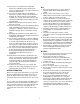
SECTION 5: KNOW YOUR LAWN TRACTOR A G B H C SLOW I J D K E F NOTE: Steering Wheel not shown for clarity. Figure 7 A B C D E F Systems Indicator Monitor/Hour Meter PTO (Blade Engage) Lever Parking Brake Lever Cruise Control Lever Shift Lever Cup Holder G H I J K Throttle / Choke Control Ignition Switch Module Brake Pedal Drive Pedal Deck Lift Lever NOTE: Any reference in this manual to the RIGHT or LEFT side of the tractor is observed from operator’s position.
Throttle / Choke Control The throttle/choke control is located on the right side of the tractor’s dash panel. This lever controls the speed of the engine and, when pushed all the way forward, closes the choke for cold starting. When set in a given position, the throttle will maintain a uniform engine speed. Ignition Switch Module Choke Position WARNING: Never leave a running machine unattended.
Systems Indicator Monitor / Hour Meter PTO (Blade Engage) Lever Battery ON OFF PTO PTO / BLADE ENGAGE 42.0 PTO (Blade Engage) LCD The PTO (Blade Engage) lever is located on the left side of the dash, next to the steering wheel. Move the PTO (Blade Engage) lever forward to engage the power to the cutting deck or other (separately available) attachments; move the PTO (Blade Engage) lever rearward to disengage the power to the attachments.
SECTION 6: OPERATING YOUR LAWN TRACTOR Safety Interlock System WARNING: Use extreme caution while operating the tractor in the REVERSE CAUTION MODE. Always look down and behind before and while backing. Do not operate the tractor when children or others are around. Stop the tractor immediately if someone enters the area. This tractor is equipped with a safety interlock system for the protection of the operator. Before each use, check the safety interlock system for proper operation.
Starting the Engine 1. Depress the brake pedal to release the parking brake and let the pedal up. 2. Move the throttle/choke control into the FAST (rabbit) position. WARNING: Do not operate the tractor if the interlock system is malfunctioning. This system was designed for your safety and protection. IMPORTANT: Do NOT use the shift lever to change the direction of travel when the tractor is in motion. Always use the brake pedal to bring the tractor to a complete stop before shifting.
NOTE: Cruise control can not be set at the tractor’s Engaged fastest ground speed. If the operator should attempt to do so, the tractor will automatically decelerate to the fastest optimal mowing ground speed. PTO Lever Disengage the cruise control using one of the following methods: • Depress the brake pedal to disengage the cruise control and stop the tractor. • Lightly depress the drive pedal.
SECTION 7: MAKING ADJUSTMENTS WARNING: Never attempt to make any 4. Determine the approximate distance necessary for proper adjustment and proceed, if necessary, to the next step. 5. From the front of the tractor, loosen the outermost hex lock nut(s) on the end(s) of the deck hanger rod. See Figure 12 or Figure 13. 6. Tighten the inner hex nut(s) front against the front hanger bracket to raise the front of the deck; loosen the hex nut to lower the front of the deck. See Figure 12 or Figure 13.
Parking Brake Adjustment Side to Side If the cutting deck appears to be mowing unevenly, a side to side adjustment can be performed. Adjust if necessary as follows: WARNING: Never attempt to adjust the brakes while the engine is running. Always disengage PTO, move shift lever into neutral position, stop engine and remove key to prevent unintended starting. 1.
Steering Adjustment 2. Remove the hex nut on the top of ball joint. See Figure 16. 3. Thread the ball joint toward the jam nut to shorten the drag link. Thread the ball joint away from the jam nut to lengthen the drag link. 4. Replace hex nut and retighten the jam nut after proper adjustment is achieved. If the tractor turns tighter in one direction than the other, or if the ball joints are being replaced due to damage or wear, the steering drag links may need to be adjusted.
SECTION 8: MAINTAINING YOUR LAWN TRACTOR NOTE: Refer to Maintenance Chart on page 31 for a TEMPERATURE / OIL VISCOSITY CHART reference of recommended maintenance intervals. WARNING: Before performing any maintenance or repairs, disengage PTO, set parking brake, stop engine and remove key to prevent unintended starting.
Changing the Engine Oil The engine oil and oil filter should be changed after every 50 hours of operation. Oil Fill Cap / Dipstick WARNING: If the engine has been recently run, the engine, muffler and surrounding metal surfaces will be hot and can cause burns to the skin. Allow the tractor to cool and use caution when removing IMPORTANT: The oil filter should be changed at every oil change interval.
Air Filter 5. Check the air cleaner base. Make sure it is secured and not damaged. Also check the air cleaner cover for damage or improper fit. Replace all damaged air cleaner components. 6. Install the precleaner over the new paper element and reinstall the element. 7. Reinstall the cover and tighten the knobs securely. The engine is equipped with a replaceable, high density paper air cleaner element. Always examine the air cleaner before starting the engine.
Lubrication 8. Check the gap using a feeler gauge and adjust, if necessary, by carefully bending the ground electrode. See Figure 20. Set the spark plug gap to 0.030 in (0.76 mm). WARNING: Before lubricating, repairing, or inspecting, always disengage PTO, set parking brake, stop engine and remove key to prevent unintended starting. Feeler Gauge Engine Spark Plug Refer to Engine on page 22 for instruction regarding all engine-related lubrication.
SECTION 9: SERVICE Tires Hex Flange Nut Wood Block WARNING: Never exceed the maximum inflation pressure shown on the sidewall of the tire. The recommended operating tire pressure is approximately 10 psi for the rear tires and 14 psi for the front tires. Do not overinflate. Uneven tire pressure could cause the cutting deck to mow unevenly. Fuse A 20 amp fuse is installed in your tractor’s wiring harness to protect the tractor’s electrical system from damage caused by excessive amperage.
5. Start the tractor (as instructed on page 17). 6. Set the tractor’s parking brake before removing the jumper cables, in reverse order of connection. 7. Allow the tractor’s engine to run for 15 minutes before shutting it off to allow the alternator time to charge the discharged battery. IMPORTANT:When replacing the blade, be sure to install the blade with the side of the blade marked ‘‘Bottom’’ (or with a part number stamped in it) facing the ground when the mower is in the operating position.
Changing the Deck Belt 6. Pull the deck support pin outward to release the deck from the deck lift arm. See Figure 25. WARNING: Be sure to shut the engine off, engage the parking brake and remove the ignition key to prevent unintended starting before removing the belt. WARNING: Avoid the possibility of a pinching injury. Do not place your fingers on the idler spring or between the belt and a pulley while removing the belt.
LX420 Belt Cover Idler Pulleys LX460 Belt Cover Idler Pulleys 29
SECTION 10: OFF-SEASON STORAGE Clean and lubricate the tractor as instructed in Section 7: MAINTAINING YOUR LAWN TRACTOR on page 22 of this manual before storing for an extended period. To empty the system, run the engine until the tank and system are empty. WARNING: Drain fuel only into an approved container outdoors, away from an open flame. Allow engine to cool. Extinguish cigarettes, cigars, pipes, and other sources of ignition prior to draining fuel.
SECTION 11: MAINTENANCE CHART Before Each Use Every 10 Hours Every 25 Hours Check Safety Interlock System Clean Hood/Dash Louvers Check Engine Oil Level Replace Air Filter Element Change Engine Oil & Filter Clean Battery Terminals Lube Front Axles and Rims Clean Engine Cooling Fins Lube Pedal Pivot Points Check Spark Plug Service Air Filter Element 31 Every 50 Hours Every 200 Hours Every Season Prior to Storing
SECTION 12: TROUBLESHOOTING Trouble Possible Cause(s) Corrective Action Engine fails to start PTO (Blade Engage) lever engaged. Parking brake not engaged. Spark plug wire disconnected. Throttle/choke control not in correct starting position. Choke not activated Fuel tank empty, or stale fuel. Blocked fuel line. Faulty spark plug. Engine flooded. Unit running with CHOKE activated. Spark plug wire(s) loose. Blocked fuel line or stale fuel. Place PTO (Blade Engage) lever in (OFF) position.
SECTION 13: SPECIFICATIONS* LX420 LX460 Fuel Tank 3.0 gal. (11.4 liters) 3.0 gal. (11.4 liters) Engine Crankcase (w/ filter) 50.75 oz. (1.5 liters) 50.75 oz. (1.5 liters) Forward Speed 0 - 5.2 mph (8.2 km/h) 0 - 5.2 mph (8.2 km/h) Reverse Speed 0 - 2.3 mph (3.7 km/h) 0 - 2.3 mph (3.7 km/h) Make Kohler Courage Kohler Courage Model SV540 SV600 Cylinders Single Single Bore 3.50 in. (89 mm) 3.70 in. (94 mm) Stroke 3.38 in. (86 mm) 3.38 in. (86 mm) Displacement 32.6 cubic in.
ELECTRIC SCHEMATIC 34
CALIFORNIA EMISSION CONTROL WARRANTY STATEMENT YOUR WARRANTY RIGHTS AND OBLIGATIONS The California Air Resources Board and MTD Consumer Group Inc are pleased to explain the evaporative emission control system warranty on your 2006 lawn mower. In California, new lawn mower must be designed, built and equipped to meet the State’s stringent anti-smog standards.
The Toro Company MANUFACTURER’S LIMITED WARRANTY FOR LAWN & GARDEN TRACTORS IMPORTANT: To obtain warranty coverage owner must present an original proof of purchase and applicable maintenance records to the servicing dealer. Please see the operator’s manual for information on required maintenance and service intervals. Without limiting the foregoing, this limited warranty does not provide coverage in the following cases: a. The engine or component parts thereof.