
Service Manual
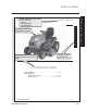


TIME SAVERS
'HP\VWL¿FDWLRQ*ORVVDU\
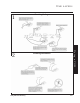
Troubleshooting
Fuel Solenoid
(Energized)
IGNITION
MODULES
SPARK PLUGSPARK PLUG
Dashed lines do not carry current
GN
GN
Y
Y
Y/W
R
R
R
R
Y/BK
GN
RRw
Rw
R
Bu
Bu
Gn
R
GN
Headlight Harness
(Headlights on)
2
G
BA1
M
Ignition Switch
(In Normal)
Brake Switch
(Brake Off)
Seat Switch
(Operator On)
PTO Switch
(PTO On)
A1 Power
E-PTO
Ground
Seat Switch
RMC Module
Rev Sw
Reverse Switch
(In Forward)
R/BK
Battery
Fuse
(20 Amp)
5
1
3
4
Relay
(Not Energized)
W/BKW/BK
Y/BK
Y/BK
PTO
Clutch
(Engaged)
W
BU/W
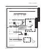
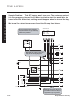
1. Test for voltage Across the PTO
clutch coil by connecting the Pos.
lead to the blue/white wire and the
Neg. lead to the white wire.
Bat. voltage - check clutch coil
resistance.
No voltage step-2.
TIP: DON'T
DISCONNECT
ANY WIRES!
When checking
for voltage you
need only touch
the terminals.
(disconnect
components
when checking
resistance.)
TIP: BE LAZY! If you have trouble
getting to a component, skip it, and go
to the next point (You can always go
back if your next reading is 0 volts.)
3. Move Neg. lead to yellow/black
wire at relay plug.
Bat. voltage - check reverse & seat
switch.
No voltage step-4.
2. Move Neg. lead to
good chassis ground.
Bat. voltage - step-3.
No voltage step-4.
4. Move Pos. lead to red wire
at PTO plug.
Bat. voltage - check PTO switch.
No voltage - check ignition switch.
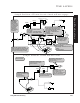
Sample Problem: GT2100 electric clutch will not engage
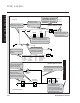
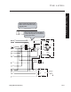
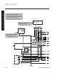
Sample Problem: LX420 will not crank
Fuel Solenoid
(Energized)
Headlight Harness
(Headlights on)
Battery
Fuse
(20 Amp)
A1
B
S
Ignition Switch
(In Start)
Starter Motor
(Energized)
Starter Solenoid
(Energized)
Brake Switch
(Brake Applied)
PTO Switch
(PTO Off)
RR
R
R
R
R RR
Rw
Or Or/bk Or/w
Or/w
Bu
Gn
Quick check:
does solenoid “click” when
key is turned to start?
If yes, you can eliminate circuit
from fuse to solenoid coil.
TIP: Use test points to
divide circuit in half.
1.Test point “a” for voltage.
Voltage is 12V. Problem is right
half of circuit.
Proceed to point “b”.
2. Test point “b” voltage reads 0V.
Problem is between “a” and “b”.
Proceed to point “c”.
3. Test point “c” Voltage is 12V.
Problem is between “c” and “b”.
Proceed to Point “d”.
4. Test point “d”. Voltage is 0V.
You disconnect the PTO switch
and find it to be defective.