
Service Manual

G
L
OSS
ARY
'
HP
\
VWL
¿
FWLRQ
*
ORVVDU
\
GLOSSARY
6
ZLWFK.H
\
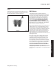
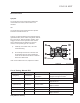
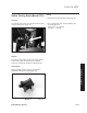
3XUSRV
H
This component provides the proper switchin
g
f
o
r
the starter, i
g
nition, accessories, and sa
f
et
y
circuits
(
Fi
g
ure 18
)
.
+
R
Z,
W
:
R
UN
V
D
etents inside the switch
g
ive it 4 positions:
S
T
O
P,
R
EVER
S
E
C
AUTI
O
N, N
O
RMAL M
O
WIN
G
, and
S
TAR
T
.
The START position is sprin
g
loaded so the
cy
linder automaticall
y
returns to N
O
RMAL M
O
WIN
G
o
nce the ke
y
is release
d
.
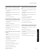
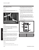
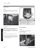
7
HVW
L
QJ
1
.
Disconnect the switch from the wirin
g
harnes
s
.
2
.
Veri
fy
that continuit
y
exists between the terminals
listed for each switch positio
n
.
Verif
y
that there is
NO
continuit
y
between terminals not listed
f
or the
s
witch position
(
Fi
g
ure 19
)
.
P
os
iti
on
C
onditio
n
O
ff G+M+A
1
R
everse Caution
(
Run 1
)
B+A 1
&
L+A
2
Normal Mowin
g
(
Run 2
)
B
+
A1
S
t
a
r
t
B+
S
+A
1
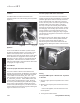
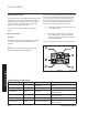
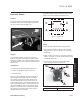
6
ZLWFK5HYHUV
H
/RFDW
L
R
Q
8
Q
L
WVHTX
L
SSH
G
Z
L
W
K
FRQVWDQWYH
O
RF
L
W\
W
UDQVPLVVLRQV
&
97
Th
e
r
e
v
e
r
se
s
wit
c
h i
s
a
tt
ac
h
ed
t
o
th
e
u
n
de
r
s
i
de
of
th
e
tractor next to the reverse lever
(
Fi
g
ure 20
)
.
)L
J
XUH
keys
w
L
G
S
M
A1
A2
B
)LJXUH swi
gn
)L
J
XUH
tr
e
v
sw