
Installation Instructions

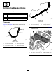
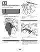

2.Placetheleftbracketatthebottomofthewelds
ofthewraprod.Usingthebracketasatemplate,
markanddrillholes(1/4inchdiameter)intothe
frame(Figure6.
g323307
Figure6
1.Leftbracket
3.Wraprod
2.Drillahole(1/4inch
diameter)here.
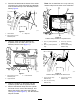
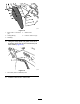
3.Usingtheupperandlowerbracketsas
templates,markanddrillholes(1/4inch
diameter)intotheframe(Figure7).
g323100
Figure7
1.Drillahole(1/4inch
diameter)here.
3.Lowerbracket
2.Upperbracket
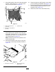
4.Cleanthesurfacesontheframenearthe
hydrauliccylinderandthehydraulichoses.
5.Removethefastenerstripsfromthecylinder
andhosecovers,removethebackings,and
adherethestripstotheframeandhydraulic
cover(Figure8andFigure9).Trimthefastener
stripsasneeded.
Note:Donotinstallthe15.6cm(6-1/8inch)
fastenerstripfromthehosecoveratthistime.
g323099
Figure8
FastenerStripLocationsforCylinderCover
1.15.2cm(6inch)fastener
strip
3.8.9cm(3-1/2inch)
fastenerstrip
2.22.9cm(9inch)fastener
strip
4.22.2cm(8-3/4inch)
fastenerstrip
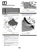
g323224
Figure9
FastenerStripLocationsforHoseCover
1.8.9cm(3-1/2inch)
fastenerstrip
3.10.8cm(4-1/4inch)
fastenerstrip
2.13.3cm(5-1/4inch)
fastenerstrip
4