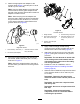
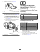
Form No. 3445-824 Rev A Universal Groomer Drive MVP Kit Reelmaster® 18-inch, 22-inch, or 27-inch EdgeSeries™ Cutting Units with 5-inch or 7-inch Reel Model No. 140-5605 Model No. 140-5607 Installation Instructions Introduction Important: Before installing this kit, ensure that you have a compatible cutting unit: 140-5605 is designed for use on Reelmaster DPA Cutting Units with a 5-inch reel. 140-5607 is designed for use on Reelmaster DPA Cutting Units with a 7-inch reel.
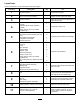
Loose Parts Use the chart below to verify that all parts have been shipped. Procedure 1 2 3 4 5 6 Description Qty. Use No parts required – Prepare the machine. Torque wrench (Not included) – Gather the tools required for setup. No parts required – Determine where on the cutting unit to install the groomer.
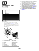
1 3 Preparing the Machine Determining the Setup No Parts Required No Parts Required Procedure Procedure 1. Park the machine on a level surface. 2. Engage the parking brake. 3. Shut off the engine and remove the key; refer to your Operator’s Manual. 4. If the cutting unit is installed, remove the cutting unit from the traction unit; refer to the Operator’s Manual for the traction unit. Use the following diagram to determine the position of the groomer kit and reel motors.
4. Restrain the reel to install the new insert; Restraining the Reel for Installing Threaded Inserts (page 22). 5. Apply medium-strength thread-locking compound (such as Blue Loctite® 243) to the threads of the new longer splined insert, and secure it to the reel shaft. Torque the insert to 115 to 128 N∙m (85 to 95 ft-lb).
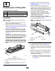
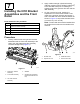
Installing the Weight Bracket and the Groomer Drive Box Parts needed for this procedure: g037064 Figure 5 1. Flange-head bolts B. 2. Support rod Install the 2 existing flange-head bolts from the inside of the cutting unit, and secure them with the 3/8 inch flange locknuts (Figure 6). 1 Weight bracket 2 Hex-socket, button-head bolt (3/8 x 3/4 inch) 1 Right (yellow) reel adapter 1 Left (green) reel adapter 1 Groomer drive box Procedure 1.
2. Attach the appropriate reel adapter to the groomer shaft (Figure 7) and torque it to 150 to 163 N∙m (110 to 120 ft-lb). Note: Use the yellow adapter on the right side of the machine; use the green adapter on the left side of the machine. Discard the unused reel adapter included in the kit.
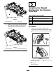
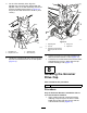
6 2. Position the idler assembly on the opposite side of the reel from the groomer drive box. 3. Install the O-ring onto the pivot-hub assembly. Installing the Idler Assembly 4. Apply anti-seize compound on the outside diameter of the pivot-hub assembly (Figure 10). 5. Secure the pivot hub over the idler assembly to the reel using 2 hex-socket bolts (Figure 10). Parts needed for this procedure: 6. Loosely install the 2 locknuts on the pivot hub (Figure 10).
7 Installing the HOC Bracket Assemblies and the Front Roller Parts needed for this procedure: 1 Left HOC bracket assembly 1 Right HOC bracket assembly 2 Shoulder bolt 1 Hardened washer 2 Flange locknut (3/8 with 5/8 hex) 2. Apply medium-strength cylindrical bonding retaining compound (such as Blue Loctite 242®) to the shoulder bolts prior to installing the adjuster arms to the groomer drive box and the idler assembly. 3.
4. On the idler assembly side, align the adjuster-arm rod of the HOC bracket with the adjuster collar on the idler assembly and secure it with a shoulder bolt as shown in Figure 13; torque the shoulder bolt to 20 to 26 N⋅m (15 to 19 ft-lb). g346926 Figure 14 g346925 3. Adjuster collar 2. Adjuster-arm rod 4. Idler assembly 5. 4. Flange nut 2. Locknut 5. Capscrew 3. Carriage bolt and flange locknut (3/8 with 5/8 inch hex) Figure 13 1. Shoulder bolt 1.
2. Install the cap as shown in Figure 15. 9 Installing the Groomer Assembly and Optional Broomer Kit Groomer and Broomer Kits Come Separately g346927 Figure 15 1. Cap 3. 2. Apply Green Loctite 609® Parts needed for this procedure: If you are installing the groomer at the left side of the machine, perform the following (Figure 16): 4 Bolt (1/4 x 1-1/2 inches) A. Remove the hex-socket screw that secures the clutch knob to the actuator shaft. 4 Jam nut 4 Shaft clamp B.
g240752 Figure 17 1. Drive-stub shaft 4. Shaft clamp (4) 2. Groomer assembly 5. Bolt (4) Torque to 5 to 7 N∙m (46 to 60 in-lb) g032403 Figure 18 3. Jam nut (4) 3. Secure the groomer to the machine as shown in Figure 17 and snug the bolts. 4. To prevent binding, set the height of cut and height of groom, then loosen the bolts. 1. Strap buckle 3. Strap 2. Retaining nut 4. Brush 3.
g032402 Figure 20 1. Brush 5. 2. Blade Loosely wrap the straps, as shown in Figure 18, around the groomer reel shaft and brushes, inserting the straps in the grooves in the brushes Figure 20.
5. 10 Adjusting the Groomer Spring Force Parts needed for this procedure: – Washer (Part No. 3256-24, not included) Procedure For low height-of-groom setups where additional spring force is required, install additional washers (Part No. 3256-24) to the eye bolt to compress the height-of-groom springs at a low height of groom. 1. Set the desired cutting unit height of cut; refer to your cutting unit Operator’s Manual. 2. Set the desired height of groom; refer to Adjusting the Groomer Height (page 16).
11 Installing the Angled Fitting For Reelmaster 3550 and 3555 Machines—#1 Front, Center Cutting Location and Kit Model 145-5605 Only Parts needed for this procedure: 1 Hydraulic fitting—45° (Part No. 340–101; sold separately) Procedure Important: For Reelmaster 3550 and 3555 machines—#1 front, center cutting location and kit Model 145-5605 only; order 45° hydraulic fitting (Part No. 340–101) and follow the procedure below. 1. Remove the hydraulic hose from the hydraulic fitting on the motor. 2.
Operation • The type of grass • The overall management program (i.e., irrigation, fertilizing, spraying, coring, overseeding, etc.) Introduction • Traffic Grooming is performed in the turf canopy above the soil level. Grooming promotes vertical growth of grass plants, reduces grain, and severs stolons, producing a denser turf. Grooming produces a more uniform and tighter playing surface for faster and truer action of the golf ball. • Stress periods (i.e.
Adjusting the Groomer Height 5. The height setting on both ends of the groomer should be identical. Adjust the height as required. DANGER Contact with the reels or other moving parts can result in personal injury. • Before making any adjustments to the cutting units, disengage the reels, set the parking brake, shut off the engine, and remove the key. • Keep your hands and clothing away from the reels or other moving parts. 1.
Height-of-Cut (HOC) and Height-of-Groom (HOG) Recommended Range Height-of-Cut (mm) Height-of-Cut (inch) Number of Rear Roller Spacers Recommended HOG = HOC Groomer Engagement Recommended HOG = HOC Groomer Engagement (mm) (inch) 6.3 0.250 0 3.1 to 6.3 0.125 to 0.250 9.5 0.375 0 4.7 to 9.5 0.187 to 0.375 9.5 0.375 1 4.7 to 9.5 0.187 to 0.375 12.7 0.500 0 6.3 to 12.7 0.250 to 0.500 12.7 0.500 1 6.3 to 12.7 0.250 to 0.500 12.7 0.500 2 6.3 to 9.5 0.250 to 0.375 15.8 0.
Transporting the Machine Testing the Groomer Performance To mow without the groomer or transport the machine, move the quick-up lever to the TRANSPORT position (Figure 26). Important: Improper or over-aggressive use of the grooming reel (i.e., too deep or too frequent grooming) may cause unnecessary stress on the turf, leading to severe damage. Use the groomer cautiously. Note: This moves the groomer reel into a raised position.
Maintenance DANGER Contact with the reels or other moving parts can result in personal injury. • Before making any adjustments to the cutting units, disengage the reels, set the parking brake, shut off the engine, and remove the key. • Keep your hands and clothing away from the reels or other moving parts. g346929 Changing the Gearbox Lubricant Figure 27 1. Remove the drain plug from the drain port. 3. Loosen the air-vent plug. 2. Remove the fill plug from the fill port.
g346930 Figure 29 Right side groomer box shown 1. Air-vent plug g346932 Figure 30 1. Shoulder bolt 2. Hardened washer 3. Drain plug 2. Fill plug Removing the Groomer Drive Box 4. Restrain the reel for removal; refer to Restraining the Reel for Removing Threaded Inserts (page 21). 5. Install the reinforcement screw (Part No. 1-803022—sold separately) to the internal threads of the groomer drive hex head and torque to 13.5 N⋅m (120 in-lb) as shown in Figure 30. 6.
Restraining the Reel Cleaning the Grooming Reel WARNING Service Interval: After each use The cutting reel blades are sharp and capable of amputating hands and feet. Clean off the grooming reel after using it by spraying it with water. Do not direct the water stream directly at the groomer bearing seals. Do not permit the grooming reel to stand in water so that the components rust. • Keep your hands and feet outside of the reel. • Ensure that the reel is restrained before servicing it.
Restraining the Reel for Installing Threaded Inserts 1. Insert a long-handled pry bar (recommended 3/8 x 12 inches with a screwdriver handle) through the front of the cutting reel, closest to the side of the cutting unit that you are torquing (Figure 33). 2. Place the pry bar against the weld side of the internal cutting reel reinforcement (Figure 33). Note: The pry bar should contact a blade at the front, the reel shaft, and a blade at the back of the back of the reel, locking it in place.
Notes:
Declaration of Incorporation The Toro Company, 8111 Lyndale Ave. South, Bloomington, MN, USA declares that the following unit(s) conform(s) to the directives listed, when installed in accordance with the accompanying instructions onto certain Toro models as indicated on the relevant Declarations of Conformity. Model No. Serial No.