
Installation Instructions


4
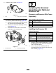
PreparingtheCuttingUnit
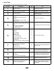
Partsneededforthisprocedure:
1
Extendedsplinedinsert(right-handthreads)
1
Extendedsplinedinsert(left-handthreads)
2
Flangelocknut(3/8inch)—Model140-5607only
Procedure
Note:Youmaydiscardallremovedpartsunless
otherwisestated.
1.Removeallcuttingunitsfromthetractionunit;
refertoyourOperator’sManual.
2.Restrainthereeltoremovetheexistingsplined
insert;refertoRestrainingtheReelforRemoving
ThreadedInserts(page21).
3.Removetheexistingsplinedinsertfromeach
endofthereelshaftusingthereeldriveshaft
tool(PartNo.TOR4112forthe5-inchreeland
PartNo.TOR4074forthe7-inchreel).Refer
toFigure3.
Important:Thesplinedinsertontheleft
sideofthecuttingunithasleft-handthreads.
Thesplinedinsertontherightsideofthe
cuttingunithasright-handthreads.
Important:Cleanthethreadsintheendof
thereelshaftofanydebrisorgreasebefore
installingthekitsplinedinsertandgroomer
box.
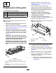
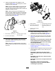
g221766
Figure3
Rightsideofcuttingunitshown
1.Extendedsplinedinsert(Torqueto115to128N∙m(85to
95ft-lb))
2.Applymedium-strengthremovablelockingcompoundto
thethreads.
4.Restrainthereeltoinstallthenewinsert;
RestrainingtheReelforInstallingThreaded
Inserts(page22).
5.Applymedium-strengththread-locking
compound(suchasBlueLoctite®243)tothe
threadsofthenewlongersplinedinsert,and
secureittothereelshaft.T orquetheinsertto
115to128N∙m(85to95ft-lb).
Important:Allowthethread-locking
compoundtocurefor15minutesbefore
continuingtheprocedure.
6.Removethecarriageboltsandlocknuts
securingtheheight-of-cut(HOC)bracketstothe
cutting-unitsideplates(Figure4).
Note:Savethecarriageboltstoinstallthenew
height-of-cutbrackets.
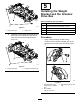
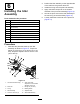
g035987
Figure4
1.Height-of-cutbracket4.Screw
2.Carriagebolt
5.Frontroller
3.Locknut
7.Loosenthescrewssecuringtheheight-of-cut
bracketstothefront-rollershaft(Figure4).
8.Removetheexistingheight-of-cutbracketsand
thefrontrollerfromthecutting-unitsideplates
(Figure4).
Note:Savethefrontrollerforlaterinstallation.
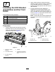
9.For7-inchcuttingunitsorifasupportrodis
installed,removethesupportrodandipthe
boltsaroundasfollows:
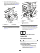
A.Removethe2ange-headboltssecuring
thesupportrod,andremovethesupport
rod(Figure5).
4