
Installation Instructions


6
InstallingtheIdler
Assembly
Partsneededforthisprocedure:
2Hex-socket-headbolt
1Pivothub
1
O-ring
1Idlerassembly
2Bearingshield
1Adjustercollar
1
Stub-shaftassembly
1
Flangenut(3/4inch)
2
Flangelocknut(3/8inch)—Model140-5605only
2
Jamlocknut(3/8inch)—Model140-5607only
Procedure
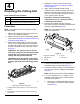
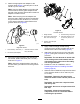
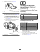
1.Assemblethepartsthatmakeuptheidler
assemblyasshowninFigure10.T orquethe
angenut(3/4inch)to37to45N∙m(27to33
ft-lb);torquetheadjustercollarto33to41N∙m
(24to30ft-lb).
g035823
Figure10
1.Hex-socket-headbolt(2)
6.Applyanti-seize
compoundontheoutside
diameterofthehub.
2.Pivothub
7.Flangenut(3/4inch)
3.O-ring
8.Bearingshield
4.Idlerassembly9.Adjustercollar
5.Locknut—3/8inch(2)10.Stub-shaftassembly
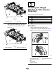
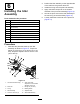
2.Positiontheidlerassemblyontheoppositeside
ofthereelfromthegroomerdrivebox.
3.InstalltheO-ringontothepivot-hubassembly.
4.Applyanti-seizecompoundontheoutside
diameterofthepivot-hubassembly(Figure10).
5.Securethepivothubovertheidlerassemblyto
thereelusing2hex-socketbolts(Figure10).
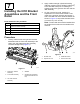
6.Looselyinstallthe2locknutsonthepivothub
(Figure10).
7