Form No. 3443-729 Rev A CE Kit Z Master® Professional 7500-D Series Riding Mower with 60in or 72in TURBO FORCE® Mower Model No. 144-0378 Model No. 144-0410 Installation Instructions Installation Loose Parts Use the chart below to verify that all parts have been shipped. Procedure 1 2 3 Description Use Qty. No parts required – Prepare the machine. No parts required – Remove the belt covers. No parts required – Remove the reverse-drive cover.
Procedure 8 9 10 11 Description Qty.
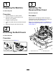
1 3 Preparing the Machine Removing the Reverse-Drive Cover No Parts Required No Parts Required Procedure 1. Park the machine on a level surface. 2. Move the motion-control levers to the NEUTRAL-LOCK position. 3. Engage the parking brake. 4. Lower the mower deck to the lowest height of cut. 5. Shut off the engine and remove the key. Procedure Remove the 3 self-tapping screws securing the reverse-drive cover and remove the cover from the right side of the mower deck (Figure 2).
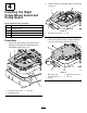
2. 4 Install 3 clips on to the right pulley-mount guard (Figure 4). Installing the Right Pulley-Mount Guard and Pulley Guard Parts needed for this procedure: 1 Right pulley-mount guard 1 Right pulley guard 3 Clip 3 Push nut 3 Flange-head bolt (1/4 x 3/4 inch) g342076 Figure 4 1. Right pulley-mount guard 3. Procedure 1. 2. Clip Secure the right pulley guard to the right pulley-mount guard using 3 flange-head bolts (1/4 x 3/4 inch) and 3 push nuts (Figure 5).
2. 5 Installing the Left Pulley-Mount Guard and Pulley Guard Secure the left pulley-mount guard to the mower deck using the previously removed button-head bolt (5/16 x 3/4 inch) and flange nut (5/16 inch) and new flange-head bolt (5/16 x 3/4 inch) and flange nut (5/16 inch) as shown in Figure 7.
4. Secure the left pulley guard to the left pulley-mount guard using 4 flange-head bolts (1/4 x 3/4 inch) and 4 push nuts (Figure 9). 2. Remove the 2 locknuts (1/4 inch) from the rubber bumpers on the cross brace (Figure 11). Retain the 2 locknuts (1/4 inch). g342088 g342112 Figure 9 1. Left pulley-mount guard 2. Push nut Figure 11 3. Flange-head bolt (1/4 x 3/4 inch) 1. Locknut (1/4 inch) 3. Cross brace 2. Rubber bumper 4. Left pulley guard 3.
Installing the Support Rods to the Skirt Guard Assembly Parts needed for this procedure: 1 Skirt guard assembly 1 Front, upper support rod 1 Front, lower support rod 1 Left, upper support rod 1 Right, upper support rod 1 Left, lower support rod 1 Right, lower support rod 5 Flange nut (5/16 inch) 1 Washer—For 72-inch decks only 5 Flange-head bolt (5/16 x 3/4 inch) Procedure 7
1. Thread 1 front, upper support rod, 1 front, lower support rod, 1 left, upper support rod, 1 right, upper support rod, 1 left, lower support rod, and 1 right, lower support rod into the skirt guard assembly (Figure 13). g342234 Figure 13 1. Right, upper support rod 3. Front, upper support rod 5. Left, upper support rod 2. Right, lower support rod 4. Front, lower support rod 6.
2. Remove the 2 button-head bolts (5/16 x 3/4 inch) and 2 flange nuts (5/16 inch) from the front of the mower deck (Figure 14). Retain the 2 button-head bolts (5/16 x 3/4 inch) and 2 flange nuts (5/16 inch). g342305 Figure 14 1. Flange nut (5/16 inch) 2. Button-head bolt (5/16 x 3/4 inch) 3. Position the assembled skirt guard underneath the frame, behind the caster wheels. 4.
5. Remove the front, right flange nut (3/8 inch) from the gearbox mount and the hex-head bolt (1/2 x 2-1/2 inches), washer, and locknut (1/2 inch) from each mower deck strut (Figure 16 and Figure 17). Retain the flange nut (3/8 inch), 2 hex-head bolts (1/2 x 2-1/2 inches), 2 washers, and 2 locknuts (1/2 inch). g342349 Figure 16 1. Flange nut (3/8 inch) 2. Gearbox mount g342307 Figure 17 Right side shown 1. Hex-head bolt (1/2 x 2-1/2 inches) 3. Locknut (1/2 inch) 2.
6. Secure the right, lower support rod to the deck strut and gearbox mount using the previously removed flange nut (3/8 inch), hex-head bolt (1/2 x 2-1/2 inches), washer, and locknut (1/2 inch) as shown in Figure 18 and Figure 19. g342352 Figure 18 1. Previously removed flange nut (3/8 inch) 3. Previously removed locknut (1/2 inch) 2. Right, lower support rod 4. Previously removed hex-head bolt (1/2 x 2-1/2 inches) g342515 Figure 19 1. Previously removed locknut (1/2 inch) 4.
7. Secure the left, lower support rod to the front, lower support rod using the previously removed hex-head bolt (1/2 x 2-1/2 inches) and locknut (1/2 inch) and new 1 flange-head bolt (5/16 x 3/4 inch), 1 washer, and 1 flange nut (5/16 inch) as shown in Figure 20. g342351 Figure 20 1. New flange-head bolt (5/16 x 3/4 inch) 4. Left, lower support rod 2. New washer—for 72-inch decks only; do not use on 60-inch decks. 3. New flange nut (5/16 inch) 5. Previously removed locknut (1/2 inch) 8. 6.
9. Secure the front, upper support rod to the front cross-shaft supports using the previously removed 2 locknuts (1/2 inch) to the front cross-shaft support (Figure 22). g342350 Figure 22 3. Front, upper support rod 1. Cross-shaft support 2. Previously removed locknut (1/2 inch) 10. Torque the 2 locknuts (1/2 inch) to 77 to 126 N∙m (57 to 93 ft-lb). 11.
8 Installing the Frame Guards Parts needed for this procedure: 1 Left frame guard 1 Right frame guard 4 Flange-head bolt (5/16 x 3/4 inch) 4 Flange nut (5/16 inch) Procedure Secure the left frame guard and right frame guard to the frame brackets using 2 flange-head bolts (5/16 x 3/4 inch) and 2 flange nuts (5/16 inch) on each side (Figure 24). g342237 Figure 24 Right side shown 1. Flange nut (5/16 inch) 3. Right frame guard 2. Right frame bracket 4.
3. 9 Secure the left CE cover and right CE cover to the seat-support plate using the previously removed 4 flange nuts (3/8 inch) as shown in Figure 26. Installing the CE Covers Parts needed for this procedure: 1 Left CE cover 1 Right CE cover Procedure 1. Tilt the operator’s seat forward. 2. Remove the 4 flange nuts (3/8 inch) from the seat-support plate (Figure 25). g342239 Figure 26 Retain the 4 flange nuts (3/8 inch). g342238 Figure 25 1. Flange nut (3/8 inch) 2.
10 Installing the Floor Pan Parts needed for this procedure: 1 Captive adapter 2 Flange-head bolt (1/4 x 3/4 inch) 2 Flat washer 2 Clip 2 Push nut Procedure 1. Install 2 clips on to the captive adapter (Figure 27). g342287 Figure 27 1. Captive adapter 2.
2. Secure the previously removed floor pan using the captive adapter, 2 flange-head bolts (1/4 x 3/4 inch), 2 flat washers, and 2 push nuts (Figure 28). g342298 Figure 28 1. Flange-head bolt (1/4 x 3/4 inch) 4. Push nut 2. Floor pan 5. Captive adapter 3.
11 Applying the Decals Parts needed for this procedure: 1 Decal 133-5623 1 Decal 144-6905—60-inch decks with 25 HP Yanmar diesel engine only 1 Decal 144-6906—72-inch decks with 25 HP Yanmar diesel engine only 1 Decal 144-6907—60-inch decks with 37 HP Yanmar diesel engine only Decal 144-6908—72-inch decks with 37 HP Yanmar diesel engine only Procedure Apply decals 133-5623 and 144-6905, 144-6906, 144-6907, or 144-6908 to the left side of the machine frame near the serial decal using the dimensions sh
Notes: