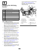
Form No. 3448-130 Rev A CE Kit 122 cm, 132 cm, or 152 cm Z Master® 4000 Series Riding Mower Model No. 145-1261 Model No. 145-1262 Model No. 145-1263 Installation Instructions Note: To create a CE bagger, install this kit on the Bagger Kit (Toro Model 78463). Safety Safety and Instructional Decals Safety decals and instructions are easily visible to the operator and are located near any area of potential danger. Replace any decal that is damaged or missing. decal117-0923 117-0923 1.
Installation Loose Parts Use the chart below to verify that all parts have been shipped. Procedure 1 2 3 4 5 6 7 8 9 10 11 Description Qty. Use No parts required – Prepare the machine. No parts required – Remove the existing side discharge chute. No parts required – Remove the OEM cover and brackets. No parts required – Remove the belt cover for the blower (if installed).
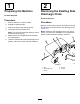
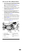
1 2 Preparing the Machine Removing the Existing Side Discharge Chute No Parts Required No Parts Required Procedure 1. Park the machine on a level surface. 2. Engage the parking brake. 3. Shut off the engine and remove the key. 4. Thoroughly clean the mower deck. Procedure Remove the bolt, spring, spacer, and locknut securing the discharge chute and remove the discharge chute (Figure 1).
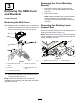
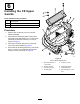
Removing the Cover Mounting Bracket 3 Removing the OEM Cover and Brackets 1. Remove the 2 bolts and 2 flange nuts that secure the cover mounting bracket to the deck (Figure 2). 2. Remove the bracket. Note: Retain the OEM cover mounting bracket, bolts, and flange nut for installation when operating the mower with the blower accessory removed. No Parts Required Removing the Belt Cover Removing the Existing Lower Support Rod If the OEM belt cover is installed, remove it as follows: 1.
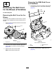
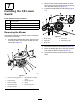
Removing the OEM Shaft Cover and Hardware 4 1. Removing the Belt Cover for the Blower (If Installed) Remove the 2 nuts and 2 washers that secure the OEM shaft cover to the blower assembly (Figure 5). No Parts Required Removing the Belt Cover for the Blower If the blower kit is installed on the machine, remove the belt cover installed from blower and drive kit as follows: 1. Remove the thumbscrew that secures the belt cover (Figure 4). g038117 Figure 4 1.
Tighten the fasteners after you install the blower; refer to Installing the Blower (page 10). 5 Important: This step applies to 122 cm mower decks only.
132 cm and 152 cm Mower Decks 1. Align the holes of the CE pulley guard to the hole in the forward deflector bracket and the outboard hole in the forward deck flange (Figure 7). Note: The CE pulley bracket wraps around the outboard edge of the deflector bracket 2. Align the CE belt-cover bracket (if not previously installed) to the holes at the rear side of the forward deck flange (Figure 7). 3.
6 Installing the CE Upper Guards Parts needed for this procedure: 1 CE shaft guard 1 CE forward guard 1 CE tensioner guard Procedure 1. Remove the 3 locknuts (1/4 inch) from the blower assembly. 2. Secure the CE tensioner guard to the blower using the 2 hex-head bolts (1/4 x 3/4 inch) and previously removed 2 locknuts (1/4 inch) as shown in Figure 8. 3. Secure the CE shaft guard using 2 locknuts (5/16 inch) and 2 washers (Figure 8). 4.
7 2. Move the idler pivot bracket toward the fixed spring post and remove the hook of the spring from the idler spring post (Figure 9). 3. Route the belt beneath the idler pulley (Figure 10). Installing the CE Lower Guard Parts needed for this procedure: 1 CE lower guard 2 Hex-head bolt (1/4 x 3/4 inch) 2 Washer (1/4 inch) 2 Locknut (1/4 inch) Removing the Blower If the blower assembly is installed, remove it from the mower deck as follows: 1.
Drilling the Mounting Holes for the CE Lower Guard 1. Installing the CE Lower Guard Note: Install the CE lower guard with the blower assembly removed from the mower deck; refer to the E-Z Vac™ Blower and Drive Kit Installation Instructions. Align the lower CE lower guard to the blower-chute bracket as shown in Figure 11. 1. Align the CE lower guard to the blower-chute bracket (Figure 11). 2.
8 2. Insert the bolt and washer through the hole in the top of the belt cover from the OEM blower and drive kit (Figure 12). 3. From the bottom of the belt cover, assemble the washer (1/4 x 1/2 inch) and retainer over the hex-head bolt threads (Figure 12). Installing the CE Belt Cover Ensure that the bolt head and washer are positioned flush with the upper surface of the belt cover and the washer and retainer are flush with the bottom surface of the cover.
9 Installing the New Lower Support Rod Parts needed for this procedure: 1 Lower support rod 1 Flange-head bolt (1/4 x 3/4 inch) 1 Locknut (1/4 inch) Procedure 1. Thread the new lower support rod through the lower skirt opening. 2. Secure the rod using 1 flange-head bolt (1/4 x 3/4 inch) and 1 locknut (1/4 inch) as shown in Figure 13. g351272 Figure 13 1. Lower support rod 3. Flange-head bolt (1/4 x 3/4 inch) 2.
10 Installing the Height-of-Cut Cover Plates Parts needed for this procedure: 2 Height-of-cut cover plate (122 cm decks) 2 Height-of-cut cover plate (132 cm and 152 cm decks) 2 Locknut (1/4 inch) 2 Carriage bolt (1/4 x 3/4 inch) 122 cm Mower Decks Secure the 2 height-of-cut cover plates to the 102 to 140 mm ranges of the height-of-cut bracket using 2 carriage bolts (1/4 x 3/4 inch) and 2 locknuts (1/4 inch) as shown in Figure 14 and Figure 15. g351823 Figure 15 Installed View g351283 Figure 14 1.
132 cm and 152 cm Mower Decks Secure the 2 height-of-cut cover plates to the 133 mm and 140 mm ranges of the height-of-cut bracket using 2 carriage bolts (1/4 x 3/4 inch) and 2 locknuts (1/4 inch) as shown in Figure 16 and Figure 17. g351284 Figure 16 1. Height-of-cut bracket 3. Height-of-cut cover plate (132 cm and 152 cm decks) 2. Locknut (1/4 inch) 4.
11 Adjusting the Engine Speed No Parts Required Procedure 1. Locate your mower and bagger combination on the Declaration of Conformity. 2. Set the engine speed (rpm) listed in the corresponding column in the Declaration of Conformity.