
Service Manual


TIME
SAVERS
2-6
Demystifi cation
G
lossary
Using this Manual
BN
BU
GY
W
PUR
R
PK
BK
Y
Y/BK
Y/W YELLOW WHITE
T
GN
OR
BROWN
BLUE
GRAY
WHITE
PURPLE
RED
PINK
BLACK
YELLOW
TAN
GREEN
ORANGE
WIRE COLOR CODES
R/W
YELLOW BLACK
RED WHITE
OR/BK
OR/W
ORNGE BLACK
ORNGE WHITE
R/BK RED BLACK
Demysti
fi
cation Guide
fi cation Guide fi
3-5
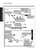
Circuits
2006
LX500,GT2100
GT2200, GT2300
Starter Motor Circuit
(ignition switch in “start”)
Spark Circuit
(ignition switch in “start”)
Fuel Solenoid
(Energized)
Headlight Harness
(Headlights on)
Battery
Fuse
(20 Amp)
A1
B
S
Ignition Switch
(In Start)
Starter Motor
(Energized)
Starter Solenoid
(Energized)
Brake Switch
(Brake Applied)
PTO Switch
(PTO Off)
R R
R
R
R
R R R
Rw
Or Or/bk Or/w
Or/w
Bu
Gn
IGNITION
MODULES
SPARK PLUG SPARK PLUG
Dashed lines do not carry current
GN
GN
Y
Y
Y/W
G
M
Ignition Switch
(In Start)
Brake Switch
(Brake Applied)
Seat Switch
(Operator On)
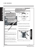
Each circuit is shown
individually. Components
not essential for circuit
function are not shown.
Additional information is
called out beneath the
title in parenthesis.
Each circuit diagram
page has a color code
legend.
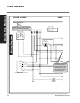
Solid lines indicate
wires that carry current.
Components with
internal circuitry are
enclosed with a dashed
line.
Each component is
named and additional
information is supplied
below in parentheses.
Circuits are drawn such that
current usually flows from left
to right (the same way you read).
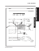
Circuit diagrams make
troubleshooting easy
and fun because each
circuit is drawn individually.
They make troubleshooting
open circuits a snap.
Wire colors are called
out at each component
(where you're most
likely to use them!)
Each component (i.e.
switches, relays,
solenoids) are drawn in
the position necessary to
make the circuit function.
Dashed lines represent wires that
are important to the circuit, but do
not carry current.