
Service Manual


rocks are not thrown.
17.
Before leaving the operator’s position behind
the handle, stop the engine and wait for all
moving parts to stop. Do not walk in front of
the mower while the engine is running. Dis-
connect the high tension wire from the spark
plug
if
the mower will be unattended.
18.
Do
not touch any part of the engine while it is
running or shortly after it is stopped because
the engine will be hot enough to cause a
burn.
Muffler
is
extremely hot. Keep
children and pets away.
I
MAINTENANCE
19.
Before the mower is serviced or adjusted,
stop the engine and remove the key from the
switch. Disconnect the high tension wire from
the spark plug to prevent the possibility of
accidental starting.
20.
To assure the mower is in safe operating
condition, keep all nuts, bolts and screws
tight. Assure the blade capscrew is tightened
to the proper torque.
21.
If
major repairs are ever needed or
if
assis-
tance is desired, contact an Authorized
TORO Service Dealer.
22.
If
the mower must be tipped when it is
serviced or adjusted, drain the gasoline from
the fuel tank.
23.
If
a guard, safety device or safety decal is
damaged, replace the defective part(s) be-
fore operating the mower.
24.
To reduce potential fire hazards, assure the
mower is free
of
excessive grease, grass,
leaves and accumulations of dirt.
25.
The grass bag must always be in good con-
dition; therefore, check it before each use to
assure the bag is not torn
or
deteriorated.
Always replace a defective grass bag.
26.
Allow the engine to cool before storing the
mower in any enclosure such as a garage or
storage shed.
Do
not store the mower near
any open flame or where gasoline fumes
may be ignited by a spark.
27.
Do not overspeed the engine by changing
the governor settings. Recommended speed
of the engine is
3000
rpm. To assure safety
and accuracy, have an Authorized TORO
Service Dealer check the engine speed with
a tachometer.
28.
At the time of manufacture the mower con-
formed to the safety standards in effect for
rotary mowers. To assure optimum perfor-
mance and continued safety certification of
the mower, use genuine TORO replacement
parts and accessories. Replacement parts
and accessories made by other manufac-
turers may result in nonconformance with
the safety standards.
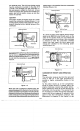
MODEL AND SERIAL NUMBERS
The TORO Two-cycle Rotary Mower has two sets
of identification numbers. There is a model and
serial number to identify the engine and a model
and serial number to identify the chassis. The
engine identification numbers are stamped into
the blower housing behind the air cleaner. Model
47PF5 engines built for
1986
have the engine
identification numbers stamped in the blower
housing above the spark plug. Engine models
47PE4 and 47PF5 have serial numbers that start
with the number
1,
2
or
3. The
number
1
indicates
a
zone start application. The number
2
indicates
BBC application and the number
3
indicates
commercial application.
The chassis identification numbers are located on
a decal on the back
of
the mower housing, between
the rear wheels.
In any correspondence concerning the mower,
supply the model and serial numbers to assure
that thecorrect information and replacement parts
are obtained. Genuine TORO replacement parts
may be ordered through your
local
TORO Autho-
rized Service Dealer.
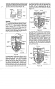
TWO-CYCLE ENGINE THEORY AND
OPERATION
Theory
Two-cycle engines have special advantages
which make their use more practical in certain
applications. Two-cycle engines are lightweight
with an excellent power to weight ratio and can
be operated in any position. They are also
notably easy to maintain and service because of
their uncomplicated design.
The TORO Two-cycle Engine used on the TORO
Rotary Mowers is a third-port, loop scavenged
design. This design name describes the path of
the fuel
/
air mixture into the crankcase and com-
bustion chamber, and the exhausting of spent
gases.
In a loop-scavenge engine, a high pressure area
is created in the crankcase by the downward
movement of the piston. Pressurized fuel-air
mixture rushes into the combustion chamber
through the intake ports and is directed toward
the cylinder head. This fresh mixture then strikes
the cylinder head and loops down forcing burnt
gases in the combustion chamber out through
1-2