
Operator's Manual
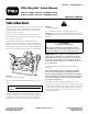
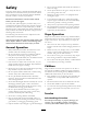
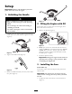
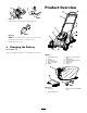
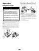
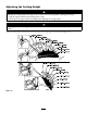
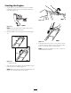

Figure 7
2. Inser t the fuse into the fuse holder ( Figure 8 ).
Figure 8
Note: Y our mo w er comes with a fuse in the o wner’ s
pac k et and another fuse in the batter y bo x.
3. Install the batter y co v er .
4. Charging the Battery
Model 20067 onl y
R efer to Charging the Batter y in the Maintenance section.
Product Overview
Figure 9
1. Cutting height lever
7. Ignition key (model 20067
only)
2. Air lter 8. Oil ll/dipstick
3. Fuel tank cap
9. Battery (model 20067 only)
4. Recoil start handle 10. Washout port
5. Blade control bar 11. Spark plug
6. Handle
12. Primer
Figure 10
1. Grass bag
3. Battery charger (model 20067
only)
2. Side discharge chute
7