
Operator's Manual


1
2
3
4
5
6
7
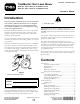
G017634
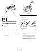
Figure14
Frontcutting-heightlever
1.A=10.8cm(4-1/4inches)5.E=5.7cm(2-1/4inches)
2.B=9.5cm(3-3/4inches)6.F=4.4cm(1-3/4inches)
3.C=8.3cm(3-1/4inches)7.G=3.2cm(1-1/4inch)
4.D=7.0cm(2-3/4inches)
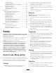
1
2
3
4
5
6
7
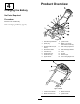
G017635
Figure15
Rearcutting-heightlever
1.A=10.8cm(4-1/4inches)5.E=5.7cm(2-1/4inches)
2.B=9.5cm(3-3/4inches)6.F=4.4cm(1-3/4inches)
3.C=8.3cm(3-1/4inches)7.G=3.2cm(1-1/4inch)
4.D=7.0cm(2-3/4inches)
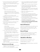
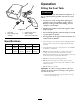
AdjustingtheHandleHeight
Youcanraiseorlowerthehandletoapositionmore
comfortableforyou.
1.Pullthehandle-lockleverrearwardtodisengagethe
handle-lockpins(Figure16).
2
G016488
3
1
Figure16
1.Handle-locklever3.Notches
2.Handle-lockpin(2)
2.Rotatethehandleandalignthedesirednotchin
thehandlebrackettothehandle-lockpins;referto
Figure16.
3.Releasethehandle-locklevertosecurethehandlein
place.
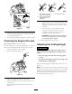
StartingtheEngine
StandardModel
Pulltherecoilhandleslowlyuntilyoufeelresistance,thenpull
itsharply.Allowtheropetoreturntotheengineslowly.
Note:Ifthemachinedoesnotstartafterseveralattempts,
contactanAuthorizedServiceDealer.
Electric-startModel
Youcanstarttheengineonanelectric-startmodelbyusing
eithertheignitionkeyortherecoil-starthandle.
•IgnitionKey:TurnandholdtheignitionkeytotheStart
position(Figure17);whentheenginestarts,releasethe
key.
Important:Donotattempttostarttheenginewith
theblade-controlbarengaged;otherwise,youmay
blowthefuse.
Note:DonotholdtheignitionkeyintheStartposition
forlongerthan5secondstopreventburningoutthe
startermotor.
10