
Operator's Manual
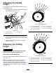
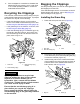


AdjustingtheHandle
Height
Youcanraiseorlowerthehandletoapositionmore
comfortableforyou.
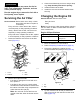
1.Pullthehandle-lockleverrearwardtodisengage
thehandle-lockpins(Figure14).
g191982
Figure14
1.Handle-locklever3.Notches
2.Handle-lockpin(2)
2.Rotatethehandleandalignthedesirednotchin
thehandlebrackettothehandle-lockpins;refer
toFigure14.
3.Releasethehandle-locklevertosecurethe
handleinplace.
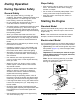
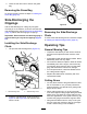
AdjustingtheCutting
Height
CAUTION
Iftheenginehasbeenrunning,themufer
willbehotandcanseverelyburnyou.
Keepawayfromthehotmufer.
Adjustthecuttingheightasdesired;refertoFigure15
andFigure16.
Note:T oraisethemachine,movethefrontand
rearcutting-heightleversforward;tolowerthe
machine,movethecutting-heightleversrearward.
Setallthewheelstothesameheightunlessspecial
circumstancesrequireotherwise;refertoOperating
Tips(page16).
g017634
Figure15
FrontCutting-HeightLever
1.A:10.8cm(4-1/4inches)5.E:5.7cm(2-1/4inches)
2.B:9.5cm(3-3/4inches)6.F:4.4cm(1-3/4inches)
3.C:8.3cm(3-1/4inches)7.G:3.2cm(1-1/4inches)
4.D:7.0cm(2-3/4inches)
g017635
Figure16
RearCutting-HeightLever
1.A:10.8cm(4-1/4inches)5.E:5.7cm(2-1/4inches)
2.B:9.5cm(3-3/4inches)6.F:4.4cm(1-3/4inches)
3.C:8.3cm(3-1/4inches)7.G:3.2cm(1-1/4inches)
4.D:7.0cm(2-3/4inches)
11