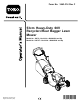
Form No. 3443-314 Rev C 53cm Heavy-Duty 60V Recycler®/Rear Bagger Lawn Mower Model No. 22275—Serial No. 400000000 and Up Model No. 22275T—Serial No. 400000000 and Up Register at www.Toro.com.
Important: With your mobile device, you can scan the QR code on the serial number decal (if equipped) to access warranty, parts, and other product information This product complies with all relevant European directives; for details, please see the separate product specific Declaration of Conformity (DOC) sheet. Introduction This rotary-blade, walk-behind lawn mower is intended to be used by residential homeowners or professional, hired operators.
Contents Safety Safety ....................................................................... 3 Safety and Instructional Decals .......................... 6 Setup ........................................................................ 8 1 Mounting the Battery Charger (Optional) ........................................................ 8 2 Removing the Cable Guard.............................. 9 3 Assembling the Lower Handle........................ 10 4 Installing the Handle ..............................
7. 8. 9. 10. 11. 12. 13. 14. machine immediately and contact an Authorized Service Dealer. adapter of the proper configuration for the power outlet if needed. Do not use a damaged or modified battery pack or battery charger, which may exhibit unpredictable behavior that results in fire, explosion, or risk of injury. If the supply cord to the battery charger is damaged, contact an Authorized Service Dealer to replace it. Do not use non-rechargeable batteries.
IV. Maintenance and Storage 1. Stop the machine, remove the electric-start button, remove the battery pack from the machine, and wait for all movement to stop before adjusting, servicing, cleaning, or storing the machine. 13. When you are not using the machine, store it indoors in a dry, secure place out of the reach of children. 14. CAUTION—A mistreated battery pack may present a risk of fire or chemical burn. Do not disassemble the battery pack.
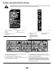
Safety and Instructional Decals Safety decals and instructions are easily visible to the operator and are located near any area of potential danger. Replace any decal that is damaged or missing. decal137-9490 137-9490 1. Read the Operator’s Manual. 2. Recycle 4. Keep away from open flames. 5. Do not expose to rain. decal144-3175 144-3175 1. Read the Operator’s Manual. 2. To start the machine, squeeze the bar to the handle and press the button. 3. Contains lithium ions; do not discard. 3.
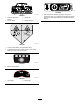
decal131-0822 131-0822 decal140-8472 1. Self-propel drive—Attention; premature wear of the transmission may occur if the belt is over-tightened; before servicing or performing maintenance, read the Operator's Manual. 140-8472 1. Read the Operator’s Manual. 2. Do not discard. 3. Residential 4. Double insulated decal112-8760 112-8760 1. Thrown object hazard—keep bystanders away. 2. Cutting/dismemberment hazard of hand or foot, mower blade—stay away from moving parts. decal137-9461 137-9461 1.
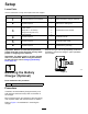
Setup Loose Parts Use the chart below to verify that all parts have been shipped. Procedure 1 2 3 4 5 6 Description Use Qty. Mounting hardware (not included) 2 Mount the battery charger (optional). No parts required – Remove the cable guard. Upper handle assembly Lower handle Bolt (5/16 x 1-3/4 inches) Flange locknut (5/16 inch) Curved washer 1 2 4 4 8 Assemble the lower handle. No parts required – Install the handle. No parts required – Install the cable guard.
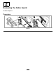
2 Removing the Cable Guard No Parts Required Procedure g328502 Figure 4 9
3 Assembling the Lower Handle Parts needed for this procedure: 1 Upper handle assembly 2 Lower handle 4 Bolt (5/16 x 1-3/4 inches) 4 Flange locknut (5/16 inch) 8 Curved washer Procedure Assemble the lower handle as shown in Figure 5. g340673 Figure 5 1. Flange locknut (5/16 inch) 4. Lower handle 2. Curved washer 5. Bolt (5/16 x 1-3/4 inches) 3.
4 Installing the Handle No Parts Required Procedure g351011 Figure 6 11
5 Installing the Cable Guard No Parts Required Procedure g350108 Figure 7 6 Assembling the Grass Bag No Parts Required Procedure g238450 Figure 8 12
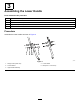
Specifications Product Overview Appropriate Temperature Ranges Charge/store the battery pack at 5°C (41°F) to 40°C (104°F)* Use the battery pack at -30°C (-22°F) to 49°C (120°F)* Use the machine at 0°C (32°F) to 49°C (120°F)* *Charging time will increase if you do not charge the battery pack within this range. Store the machine, battery pack, and battery charger in an enclosed clean, dry area. g346507 Figure 9 1. Self-propel drive bar 5. Rear deflector 2. Handle 6. Battery compartment 3.
Operation Before Operation Installing the Battery Pack Important: Use the battery pack only in temperatures that are within the appropriate range; refer to Specifications (page 13). 1. Make sure that the vents on the battery are clear of any dust and debris. 2. Lift up the battery-compartment lid (A of Figure 11). 3. Line up the cavity in the battery pack with the tongue on the machine and slide the battery pack into the compartment until it locks into place (B of Figure 11). 4.
Adjusting the Cutting Height WARNING Adjusting the cutting-height levers could bring your hands into contact with a moving blade and result in serious injury. • Shut off the motor, remove the electric-start button, and wait for all moving parts to stop before adjusting the cutting height. • Do not put your fingers under the housing when adjusting the cutting height. Adjust the cutting height as desired. Set all wheels to the same cutting height (Figure 12).
Adjusting the Handle Height You can raise or lower the handle in 1 of 3 positions that is more comfortable for you (Figure 13). g331956 Figure 13 1. Remove both handle bolts and corresponding nuts. 2. Move the handle to the desired height position. 3. Secure the handle with the previously removed bolts and corresponding nuts.
During Operation Starting the Machine 1. 2. 3. 4. Ensure that the battery pack is installed in the machine; refer to Installing the Battery Pack (page 14). Insert the electric-start button into the electric starter switch (A of Figure 14). Squeeze the blade-control bar and hold it to the handle (B of Figure 14). Press the electric-start button and keep it pressed until the motor starts (C of Figure 14).
g303153 Figure 15 Removing the Grass Bag DANGER The machine can throw grass clippings and other objects through an opening in the machine housing. Objects thrown with enough force could cause serious personal injury or death to you or to bystanders. • Never remove the grass bag and then start the machine without the discharge plug installed on the machine. • Never open the rear deflector on the machine when the machine is running. 1. Shut off the machine and wait for all moving parts to stop. 2.
Operating the Self-Propel Drive To operate the self-propel drive, squeeze the self-propel drive bar toward the handle and hold it in place (Figure 16). g337279 Figure 17 1. AUTO position 2. MAX position Shutting Off the Machine 1. Release the blade-control bar (A of Figure 18). 2. Remove the electric-start button from the electric starter (B of Figure 18). 3. Remove the battery pack; refer to Removing the Battery Pack from the Machine (page 19).
Cutting Leaves Operating Tips • After cutting the lawn, ensure that half of the lawn shows through the cut leaf cover. You may need to make more than a single pass over the leaves. General Mowing Tips • Avoid striking solid objects with the blade. Never • If there are more than 13 cm (5 inches) of leaves deliberately mow over any object. on the lawn, mow at a higher cutting height and then again at the desired cutting height.
After Operation Charging the Battery Pack Important: The battery pack is not fully charged when you purchase it. Before using the tool for the first time, place the battery pack in the charger and charge it until the LED display indicates the battery pack is fully charged. Read all safety precautions. Important: Charge the battery pack only in temperatures that are within the appropriate range; refer to Specifications (page 13).
Cleaning under the Machine Service Interval: After each use To ensure the best performance, keep the underside of the machine clean and clean under the machine soon after you have completed mowing. Be especially careful to keep the kickers free of debris (Figure 20). g002600 Figure 21 1. Right, rear wheel 5. When no more clippings come out, stop the water and move the machine to a dry area. 6. Run the motor for a few minutes to dry the underside of the machine.
Maintenance Recommended Maintenance Schedule(s) Maintenance Service Interval Maintenance Procedure After the first 25 hours • Tighten any loose fasteners. Before each use or daily • Inspect the mower blades for wear or damage. • Inspect the accelerator for wear or damage. • Check the stopping time of the blade brake. The blade must stop within 3 seconds of releasing the blade-control bar; if it does not, contact an Authorized Service Dealer for repair.
Maintaining the Blade Inspecting the Blade Always mow with a sharp blade. A sharp blade cuts cleanly and without tearing or shredding the grass blades. Service Interval: Before each use or daily—Inspect the mower blades for wear or damage. 1. Shut off the machine and wait for all moving parts to stop. 2. Remove the battery pack; refer to Removing the Battery Pack from the Machine (page 19). 3. Tip the machine onto its side as shown in Figure 23.
Removing the Blade Carefully examine the accelerator for excessive wear (Figure 25). Because sand and abrasive material can wear away the metal (especially in the area shown as item 2 in Figure 25), check the accelerator before using the machine. If you notice that a tab on the accelerator has been worn down to a sharp edge or there is a crack, replace the accelerator. 1. Grasp the end of the blade using a rag or a thickly padded glove. 2.
Preparing the Battery Pack for Recycling Installing the Blade 1. Install a sharp, balanced Toro blade, the accelerator, the lock washer, and the blade bolt. The sail of the blade must point toward the top of the mower housing for proper installation. Important: Upon removal, cover the terminals of the battery pack with heavy-duty adhesive tape. Do not attempt to destroy or disassemble the battery pack or remove any of its components. Note: Torque the blade bolt to 82 N∙m (60 ft-lb).
Storage To prepare the machine for off-season storage, perform the recommended maintenance procedures; refer to Maintenance (page 23). Always shut off the machine, wait for all moving parts to stop, and allow the machine to cool before adjusting, servicing, cleaning, or storing it. Store the machine in a cool, clean, dry place. Cover the machine to keep it clean and protected.
Troubleshooting Perform only the steps described in these instructions. All further inspection, maintenance, and repair work must be performed by an authorized service center or a similarly qualified specialist if you cannot solve the problem yourself. Problem Possible Cause Corrective Action The machine does not run or does not run continuously. 1. The battery is not fully installed in the machine. 1.
Problem Possible Cause Corrective Action The LED indicator light on the battery charger is red. 1. The battery charger and/or battery pack is over or under the appropriate temperature range. 1. Unplug the battery charger and move the battery charger and battery pack to a place where it is dry and the temperature is between 5°C (41°F) and 40°C (104°F). The LED indicator light on the battery charger is blinking red. 1. There is an error in the communication between the battery pack and the charger. 1.
Notes:
Notes:
EEA/UK Privacy Notice Toro’s Use of Your Personal Information The Toro Company (“Toro”) respects your privacy. When you purchase our products, we may collect certain personal information about you, either directly from you or through your local Toro company or dealer.