FORM NO. 3321–119 DINGO 220–D Traction Unit Model No. 22302 – 890001 & Up Operator’s Manual IMPORTANT: Read this manual carefully. It contains information about your safety and the safety of others. Also become familiar with the controls and their proper use before you operate the product.
Introduction Thank you for purchasing a Toro product. All of us at Toro want you to be completely satisfied with your new product, so feel free to contact your local Authorized Service Dealer for help with service, genuine replacement parts, or other information you may require. Whenever you contact your Authorized Service Dealer or the factory, always know the model and serial numbers of your product.
Contents Contents . . . . . . . . . . . . . . . . . . . . . . . . . . . . . . . Safety . . . . . . . . . . . . . . . . . . . . . . . . . . . . . . . . . Safe Operating Practices . . . . . . . . . . . . . . Slope Chart . . . . . . . . . . . . . . . . . . . . . . . . . Safety and Instruction Decals . . . . . . . . . . Assembly . . . . . . . . . . . . . . . . . . . . . . . . . . . . . . Loose Parts . . . . . . . . . . . . . . . . . . . . . . . . . Install Valve Levers . . . . . . . . . . . . . . . . . .
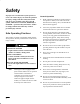
Safety Improper use or maintenance by the operator or owner can result in injury. To reduce the potential for injury, comply with these safety instructions and always pay attention to the safety alert symbol, which means CAUTION, WARNING, or DANGER—“personal safety instruction.” Failure to comply with the instruction may result in personal injury or death. Safe Operating Practices General Operation 1.
Safety 12. Never jerk the control levers, use a steady motion. 13. Keep hands, feet, hair and loose clothing away from any moving parts while engine is running. 14. Stop the engine before leaving the operator’s position. 15. Operate only in daylight or good artificial light. • Use slow speed. Before starting, put pump selector valve in slow (turtle) position so that you will not have to stop or shift while on the slope.
Safety Children 7. Tragic accidents can occur if the operator is not alert to the presence of children. Children are often attracted to the machine and the work activity. Never assume that children will remain where you last saw them. The following requirements must be followed to prevent injury to children. Use extra care when handling gasoline and other fuels. They are flammable and vapors are explosive. A. Use only an approved container. B.
Safety Slope Chart Read all safety instructions on pages 2–4.
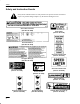
Safety Safety and Instruction Decals Safety decals and instructions are easily visible to the operator and are located near any area of potential danger. Replace any decal that is damaged or lost. On Loader Cross Bar (Part No. 98–4682) Near Oil Fill (Part No. 85–4730) On Control Panel (Part No. 98–4676) On Front Control Panel (Part No. 98–4677) On Upper Arms (2) (Part No. 98–9051) CAUTION DO NOT USE STARTING FLUID On Control Panel (Part No.
Assembly Loose Parts Note: Use the chart below to verify all parts have been shipped. DESCRIPTION QTY. USE Loader Arm Cylinder Locks 2 Clevis Pin 2 Cotter Pin 2 Valve Lever 2 Key 2 Training Video 1 View before operating machine Operator’s Manual 1 Read before operating machine Registration card 1 Fill out and return to Toro Use to lock loader arms during maintenance Install valve levers Install Valve Levers 1. 2.
Specifications General Specifications: Approved Attachments (without operator and without attachments) Overall width 40.5 inches (103 cm) Overall length 60.0 inches (152 cm) Overall height 49.0 inches (125 cm) Weight 1680 lbs (762kg) Rated operating capacity 525 lbs (with 200 lb operator & standard bucket) (238 kg) Tipping capacity l050lbs (with 200 lb operator & standard bucket) (476kg) Wheelbase 28.5 inches (72 cm) Dump height (with std. bucket) 48.
Before Operating Each time before operating your machine, check the following: Filling the Fuel Tank 1. Park the machine on a level surface, lower the loader arms and turn the ignition key to “OFF” to stop the engine. Remove the key. 2. Clean around the fuel tank cap and remove the cap. Use a funnel and add diesel fuel to the fuel tank, until the level is 1/4 to 1/2 inch (6 mm to 13 mm) below the bottom of the filler neck. This space in the tank allows fuel to expand.
Check Before Operating Open Fuel Cap Vent 1. Rotate screw on fuel cap to open vent before operating. 2. Close fuel cap vent when transporting machine on trailer to prevent fuel spillage. Draining Water from the Fuel Filter Inspect fuel filter bowl, daily, for water or other contaminants. If water or other contaminants are present, they must be removed before commencing operation. 1. Close fuel shut–off above filter. 2. Unscrew nut securing bowl to filter head.
Check Before Operating Checking Oil Level 2 1 1. Park the machine on a level surface, lower the loader arms and turn the ignition key to “OFF” to stop the engine. Remove the key. 2. Clean around the oil dipstick (Fig. 3 & 4) so dirt cannot fall into the filler hole and damage the engine. 3. Pull out the oil dipstick and wipe the metal end clean. 4. Slide the oil dipstick fully into the filler tube. Pull the dipstick out and look at the metal end.
Check Before Operating Check the Cooling System Check Radiator Coolant The cooling system is filled with a 50/50 solution of water and permanent ethylene glycol anti–freeze. Check the level of coolant at the beginning of each day before starting the engine. 1 Figure 5 1. Filler Cap POTENTIAL HAZARD • Coolant is hot and pressurized. WHAT CAN HAPPEN • Discharge of hot pressurized coolant can cause severe burns. HOW TO AVOID THE HAZARD • Do not remove the radiator cap when the engine is hot.
Check Before Operating Remove Debris From Machine IMPORTANT: Operating the engine with a blocked or plugged radiator will result in engine damage from overheating. 1. 2. 3. 4. Park the machine on a level surface, lower the loader arms and turn the ignition key to “OFF” to stop the engine. Remove the key. Check for debris on the air filter pre–cleaner. Wipe away debris before each use and/or during use, if required. Debris can build up in the engine area.
Check Before Operating 1 Figure 6 1. Filler neck cap Tire pressure Maintain the air pressure in the tires as specified. Check the tires when they are cold to get the most accurate pressure reading. Pressure: 15–22 psi Note: It may be beneficial to use lower tire pressure when operating in sandy soil conditions. Note: Tires are filled with a water/anti–freeze mixture for additional ballast. 1 m–1872 Figure 7 1.
Operation Think Safety First Please carefully read all the safety instructions on pages 2–8 and view the training video. Following these instructions could help you or bystanders avoid injury. Controls Become familiar with all the controls (Fig. 8) before you start the engine and operate the machine. Traction control levers To go forward, slowly push the traction control levers forward. To go straight, apply equal force to both traction control levers.
Operation Attachment tilt lever Flow divider control To tilt attachment forward, slowly push the attachment tilt lever forward. Move flow divider control to twelve–o’clock position (normal operating position) for no flow division. When moving control to nine–o’clock position, flow is diverted to the attachments and less is available to the wheels and loader arms. This allows for greater concentration of power where it’s needed most.
Operation Starting and Stopping Engine Starting 1. Stand on platform. 2. Open fuel cap vent. 3. Move the auxiliary hydraulics valve lever to neutral. POTENTIAL HAZARD • Attachment may move during starting Stopping 1. Move the throttle lever to “SLOW”. 2. Lower loader arms to the ground. 3. Turn the ignition key to “OFF”. Note: If the engine has been working hard or is hot, let it idle for a minute before turning the ignition key “OFF.” This helps cool the engine before it is stopped.
Operation Driving Forward or Backward Stopping the Machine The throttle control regulates the engine speed as measured in rpm (revolutions per minute). Place the throttle control in the “FAST” position for best performance. To stop the machine, move the traction control levers to neutral, lower loader arms to the ground, and turn the ignition key to “OFF” to stop the engine. Remember to remove the key from the key switch. Note: Throttle position can be utilized to operate at slower speeds.
Operation Moving A Non Functioning Machine IMPORTANT: Never tow the machine without disconnecting the traction drive chains because hydraulic damage may occur. To Move the Machine Installation 1. Start engine. 2. Raise loader arms to fully raised position. 3. Turn the ignition key to “OFF” to stop the engine. 4. Position a loader arm cylinder arm lock over each hydraulic cylinder rod. 1. Turn the ignition key to “OFF” to stop the engine. 5.
Operation Attachments 7. Move the auxiliary hydraulics lever to the forward, backward and back to neutral position to relieve hydraulic pressure at the hydraulic couplers. 8. Remove protective covers from hydraulic couplers on machine. Connect covers together to prevent contamination during operation. 9. Slide collar back on hydraulic coupler and connect attachment couplers to machine couplers. Connecting IMPORTANT: Use only Toro approved attachments.
Operation Transporting and Securing IMPORTANT: Do not operate or drive machine on roadways. IMPORTANT: When transporting machine on a trailer, always use the following procedure: 1. Lower the loader arms. 2. Turn the ignition key to “OFF” to stop the engine. 3. Secure the machine to the trailer with chains or straps using the rear platform support openings to secure rear of machine and loader arms/mount plate to secure front of machine. 4. Close the fuel vent cap before transporting machine.
Maintenance Service Interval Chart Service Operation Hydraulic Fluid–check level Each Use Initial 8 Hours 25 Hours X 50 Hours 100 Hours 200 Hours Hydraulic Fluid–change X Hydraulic Filter–change Engine Oil—check level Initial X X Engine Oil—change* Initial Engine Oil Filter–change (200 hours or every other oil change) Traction Drive Chain Tension–check X Initial Initial X X Traction Drive Chain–lubrication X Wheel Nuts–tighten Initial Chassis—grease** X Air Cleaner Pre–Cleaner—empt
Maintenance POTENTIAL HAZARD • If you leave the key in the ignition switch, someone could start the engine. WHAT CAN HAPPEN • Accidental starting of the engine could seriously injure you or other bystanders. HOW TO AVOID THE HAZARD • Remove the key from the ignition switch and and disconnect negative battery cable from battery before you do any maintenance. Air Cleaner 1. Dump dust out of the dust cup. After cleaning cup and baffle, assemble and reinstall both parts.
Maintenance Washing Method IMPORTANT: Do not remove plastic fin assembly because washing removes dust from beneath fins. A. Prepare a solution of filter cleaner and water and soak filter element about 15 minutes. Refer to directions on filter cleaner carton for complete information. B. C. Place bright light inside filter. 2. Rotate filter slowly while checking for cleanliness, ruptures, holes, and tears. Replace defective filter element. 3. Check fin assembly, gasket, and screen for damage.
Maintenance Engine Oil Service Interval/Specification POTENTIAL HAZARD • Components will be hot if the traction unit has been running. Change oil: • After the first 50 operating hours. • After every 100 operating hours. WHAT CAN HAPPEN • Touching hot components can cause burns. HOW TO AVOID THE HAZARD • Allow the traction unit to cool before performing maintenance or any touching components. Oil Type: High–quality detergent oil classified “API Service CD” or higher for diesel engines.
Maintenance Changing the Engine Oil Filter Service Interval/Specification Replace the oil filter after the initial 50 hours of operation and then after every 200 hours. 1. Drain the oil from the engine; refer to Changing/Draining Oil, page 25. 2. Place a drip pan beneath the oil drip tray to receive oil from the oil filter and oil passages in the engine. 3. Turn the filter counterclockwise to remove it. Figure 11 1. Oil filler cap 6. Replace the filler cap. 7.
Maintenance Changing the Engine Coolant POTENTIAL HAZARD • Coolant is hot and pressurized. 3. Open both coolant drain valves at the bottom of the radiator and allow coolant to flow into a drain pan. When coolant stops flowing, close the drain valves. 4. Slowly fill the radiator with a 50/50 mixture of water and permanent ethylene glycol anti–freeze. Fill the radiator completely,.8 gal. (3.1 l) Install the radiator cap. 5. Slowly fill the radiator until the level reaches the upper line.
Maintenance Greasing and Lubrication Fuel Filter Grease all bearings, bushings and pivot joints every 8 operating hours. Grease more frequently when operating conditions are extremely dusty or sandy and immediately after every washing. Replace the fuel filter after every 400 operating hours or yearly, whichever occurs first. Grease Type: General-purpose grease. How to Grease 1. Lower the loader arms and turn the ignition key to “OFF” to stop the engine. Remove the key. 2.
Maintenance 4. Remove and inspect fuel filter. Replace if dirty. 5. Re–install bowl to filter head. Make sure O–ring is positioned properly between bowl mounting nut and filter head. 6. Open fuel shut–off on filter. 7. Open bleed screws on filter mounting head to re–fill bowl with fuel. Close bleed screws. 3 Bleeding Fuel System Bleeding of the fuel system is required if: • Initial start up of a new machine or a machine that has been stored. • Engine has ceased running due to lack of fuel.
Maintenance 4. Open (2) bleed screws, on side of fuel filter mounting head, allowing bowl to re–fill with fuel. Close bleed screws when bowl is filled. 5. On right side of engine, locate air vent plug on top of the fuel injection pump. Open plug. 6. When a steady stream of fuel flows out of vent plug, close plug. Fuel Tank Draining The Fuel Tank POTENTIAL HAZARD • Under certain conditions fuel is extremely flammable and highly explosive.
Maintenance Hydraulic System Replacing the Hydraulic Filter 6. Start engine and let run for about two minutes to purge air from the system. Stop the engine and check for leaks. 7. Check fluid level in hydraulic tank and add to raise level to mark on dipstick. DO NOT OVER FILL. Change the hydraulic filter: • After the first 8 operating hours. • After every 400 operating hours. Changing the Hydraulic Fluid 1.
Maintenance Check Hydraulic Lines After every 100 operating hours, check hydraulic lines and hoses for leaks, loose fittings, kinked lines, loose mounting supports, wear, weather and chemical deterioration. Replace all moving hydraulic hoses every 1500 hours or 2 years, which ever come first. Make necessary repairs before operating. Adjusting Traction Drive Chains Check Drive Chain Tension. Drive chains should have about 1–1/2 to 2–1/2 inches of slack at the bottom.
Maintenance Fan Belt Adjustment Engine RPM Make sure belt is properly tensioned to prevent engine overheating and allow proper battery charging. Check belt midway in span of belt. Also check the belt for cracks and tears. Check and adjust engine rpm every 400 hours to insure proper engine performance. The fan belt should have a maximum deflection of .25–.35 inch (7–9mm) with a 22 pound (10Kg) load applied. 1.
Maintenance Battery Check the electrolyte level in the battery every 25 hours. Always keep the battery clean and fully charged. Use a paper towel to clean the battery case. If the battery terminals are corroded, clean them with a solution of four parts water and one part baking soda. Apply a light coating of grease to the battery terminals to reduce corrosion. IMPORTANT: Do not overfill the battery because electrolyte (sulfuric acid) can cause severe corrosion and damage to the chassis. 4.
Maintenance Cleaning and Storage 1. Lower the loader arms and turn the ignition key to “OFF” to stop the engine. Remove the key. 2. Remove dirt and grime from the external parts of the entire machine, especially the engine. Clean dirt and chaff from the outside of the engine. IMPORTANT: You can wash the machine with mild detergent and water. Do not pressure wash the machine. Avoid excessive use of water, especially near the control panel, engine, hydraulic pumps and motors. 3.
Troubleshooting PROBLEM The starter does not crank. The engine cranks, but will not start. 36 POSSIBLE CAUSES CORRECTIVE ACTION 1. The electrical connections are corroded or loose. 1. Check the electrical connections for good contact. 2. A fuse is blown or loose. 2. Correct or replace the fuse. 3. The relay or switch is defective. 3. Contact your Authorized Service Dealer. 4. The battery is discharged. 4. Charge the battery or replace it. 5. A faulty starter or starter solenoid. 5.
Troubleshooting PROBLEM The engine cranks, but will not start (continued). The engine starts, but does not keep running. The engine runs, but knocks or misses. POSSIBLE CAUSES 9. Slow cranking speed. CORRECTIVE ACTION 9. Check the battery, oil viscosity and starting motor (contact your Authorized Service Dealer). 10. The air cleaner element is dirty. 10. Clean or replace. 11. Low compression. 11. Contact your Authorized Service Dealer. 12. The injection nozzles are faulty. 12.
Troubleshooting PROBLEM The engine runs, but knocks or misses (continued). The engine will not idle. The engine overheats. 38 POSSIBLE CAUSES CORRECTIVE ACTION 3. There is air in the fuel. 3. Bleed nozzles and check for air leaks at the fuel hose connections and fittings between the fuel tank and engine. 4. The injection nozzles are faulty. 4. Contact your Authorized Service Dealer. 5. Low compression 5. Contact your Authorized Service Dealer. 6. The injection pump timing is incorrect.
Troubleshooting PROBLEM The engine overheats (continued). The engine loses power. Excessive black smoke from exhaust. POSSIBLE CAUSES CORRECTIVE ACTION 6. The thermostat is faulty. 6. Contact your Authorized Service Dealer. 7. The fan belt is loose or broken. 7. Contact your Authorized Service Dealer. 8. Incorrect fuel is in the fuel system. 8. Drain and flush the fuel system; add fresh fuel. 9. Injection timing is incorrect. 9. Contact your Authorized Service Dealer. 10.
Troubleshooting PROBLEM POSSIBLE CAUSES CORRECTIVE ACTION Excessive black smoke from exhaust (continued). 6. Excessive loading. 6. Reduce load; use lower ground speed. Excessive white smoke from exhaust. 1. The engine temperature is low. 1. Check the thermostat. 2. The glow plugs are inoperative. 2. Check the fuse, glow plugs and wiring. 3. The fuel injection nozzles are faulty. 3. Contact your Authorized Service Dealer. 4. The injection pump timing is incorrect. 4.
The Toro SiteWorkT Systems Product Line One Year Limited Warranty The Toro Company warrants your Toro SiteWorkT Systems Product (Product") to be free from defects in materials or workmanship for the period of time listed below. Where a warrantable condition exists, Toro will repair the Product at no cost to you including diagnosis, labor, parts, and transportation. This warranty begins on the date the Product is delivered to the original retail purchaser.