
Service Manual


HY13-1512-006-M1/USA
Torqmotor™ Service Procedure
TC, TS, TB, TE, TJ, TF, TG, TH and TL Series
Parker Hannifi n Corporation
Hydraulic Pump/Motor Division
Greeneville, TN 37745 US
45
Assemble
seal &
commutator
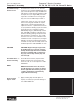
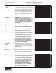
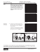
19. Assemble a new seal ring (3) fl at side up,
into commutator (5) and assemble com-
mutator over the end of drive link (10) onto
manifold (7) with seal ring side up. SEE
FIGURE 59, 60.
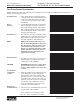
Assemble shuttle
valve parts into
end cover
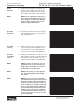
20. If shuttle valve components items #21, #22,
#23, #24 were removed from the end cover
(2) turn a plug (21) with a new o-ring (22),
loosely into one end of the valve cavity in
the end cover. Insert a spring (23) the valve
(24) and the second spring (23) into the
other end of the valve cavity. Turn the sec-
ond plug (21) with a new o-ring (22) loosely
into the end cover valve cavity. 3/16 inch
Allen wrench required. SEE FIGURE 61.
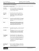
Assemble relief
valve parts in
end cover
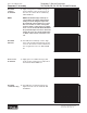
21. If relief valve components items #21, #22,
#24 were removed from the end cover (2)
assemble a new o-ring (22) on the two
plugs (21). Assemble a two piece relief valve
(24) in each of the plugs, with the large end
of the conical spring into the plug fi rst and
the small nut of the other valve piece in the
small end of the conical spring. Turn each
of the plug and relief valve assemblies into
the end cover loosely to be torqued later.
3/8 inch Allen or 1 inch Hex socket required.
SEE FIGURE 62.
Figure 59
Figure 60
Figure 61
Figure 62
Torqmotor™ Assembly