Form No. 3327-124 Dingo 320-D Dingo Compact Utility Loader Model No.
Warning Specifications . . . . . . . . . . . . . . . . . . . . . . . . . . . . . . . Attachments . . . . . . . . . . . . . . . . . . . . . . . . . . . . . Stability Data . . . . . . . . . . . . . . . . . . . . . . . . . . . . Before Operating . . . . . . . . . . . . . . . . . . . . . . . . . . . . Adding Fuel . . . . . . . . . . . . . . . . . . . . . . . . . . . . . Draining Water from the Fuel Filter . . . . . . . . . . Checking the Oil Level . . . . . . . . . . . . . . . . . . . .
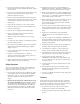
Safety or Service Representative provide exact information about your specific product. You will find the model and serial number plate at the location shown in Figure 1. Improper use or maintenance by the operator or owner can result in injury. To reduce the potential for injury, comply with these safety instructions and always pay attention to the safety alert symbol, which means CAUTION, WARNING, or DANGER—“personal safety instruction.
• Do not exceed the rated operating capacity, as the traction unit may become unstable which may result in loss of control. • Raising the loader arms on a slope will affect the stability of the machine. Whenever possible, keep the loader arms in the lowered position when on slopes. • Do not carry a load with the arms raised. Always carry loads close to the ground. Do not step off of the platform with the load raised. • Removing an attachment on a slope will make the rear of the traction unit heavy.
• Before and while backing, look behind and down for small children. • Battery gases can explode. Keep cigarettes, sparks and flames away from the battery. • Never carry children. They may fall off and be seriously injured or interfere with safe traction unit operation. • Keep your body and hands away from pin hole leaks or nozzles that eject high pressure hydraulic fluid. Use cardboard or paper to find hydraulic leaks.
Slope Chart 6
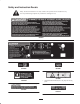
Safety and Instruction Decals Safety decals and instructions are easily visible to the operator and are located near any area of potential danger. Replace any decal that is damaged or lost. 98-9051 99-3157 93-6680 98-8220 93-6681 105-8404 1. Cutting/dismembermenthazard, fan—stay away from moving parts.
1 1 #93-7814 1. Entanglement hazard—stay away from moving parts 98-8219 1. Fast 2. Throttle 3. Slow 93-9084 1. Lift point 98-8235 1. Fast 2. Traction drive 2. Tie-down point 98-4677 3. Slow Assembly Note: Determine the left and right side of the machine from the normal operating position. Loose Parts Note: Use the chart below to verify that all parts have been shipped. DESCRIPTION QTY.
1 Danger Battery electrolyte contains sulfuric acid which is a deadly poison and causes severe burns. • Do not drink electrolyte and avoid contact with skin, eyes or clothing. Wear safety glasses to shield your eyes and robber gloves to protect your hands. • Fill the battery where clean water is always available for flushing the skin. m–3883 Figure 2 1. Speed selector lever 4. Remove the filler caps from the battery. 5.
Note: Ensure that the battery cables do not contact any sharp edges or each other. 4 14. Install the battery cover (Fig. 3). 2 1 3 Specifications Overall width 40.5 in. (103 cm) Overall length 60 in. (152 cm) Overall height 49 in. (125 cm) Weight 1722 lb. (783 kg) 1254 Figure 5 1. Positive post 2. Negative post 3. Charger red (+) wire 4. Charger black (–) wire Rated operating capacity (with 200 lb operator and std. bucket) 524 lb. (238 kg) Tipping capacity (with 200 lb operator and st.
Stability Data The following table lists the maximum slope recommended for the traction unit in the positions listed in the table. Slopes over the listed degree may cause the traction unit to become unstable. The data in the table assumes that the loader arms are fully lowered and that the factory installed tires are on the traction unit, inflated to the recommended pressure; raised arms and other tire types or pressure may affect the stability.
Adding Fuel Draining Water from the Fuel Filter Danger Drain water or other contaminants from the fuel filter daily. In certain conditions, fuel is flammable and explosive. A fire or explosion can burn you and others and can damage property. 1. Stop the engine and remove the key. 2. Open the rear access cover; refer to Opening the Rear Access Cover, page 23. • Fill the fuel tank outdoors, in an open area, when the engine is cold. Wipe up any fuel that spills.
10. Replace the filler cap and dipstick. 4 2 1 3 m–4591 Figure 8 1. Filler Cap 1 m–4594 m–3219 Removing Debris from the Traction Unit Figure 7 1. Oil dipstick 2. Filler cap 3. Valve cover 4. Metal end Important Operating the engine with a blocked radiator, may result in engine damage from overheating. 11. Close the rear access cover. 1. Park the traction unit on a level surface, raise the loader arms, and install the cylinder locks; refer to Using the Cylinder Locks, page 19.
2. Park the traction unit on a level surface, raise the loader arms, and install the cylinder locks; refer to Using the Cylinder Locks, page 19. 9. Install the front access cover. 10. Remove and store the cylinder locks (refer to Using the Cylinder Locks, page 19) and lower the loader arms. 3. Stop the engine and remove the key. 4. Remove the front access cover, refer to Removing the Front Access Cover, page 23. Tire pressure 5. Clean the area around the filler neck of the hydraulic tank (Fig. 9).
17 6 14 4 15 14 5 6 4 13 12 3 2 18 7 11 10 m 4592 1 16 9 8 m 4599 18 Figure 11 1. 2. 3. 4. 5. Mount plate Tilt cylinder Auxiliary hydraulic couplers Loader arms Front access cover 6. 7. 8. 9. 10. Fuel tank Wheel Lift cylinder Operator platform Rear access cover (open) 11. 12. 13. 14. Engine Air filter Control panel Lift points 15. 16. 17. 18. Handle Battery Indicator lights Tow valves Controls Caution Become familiar with all the controls (Fig.
Throttle Lever Move the speed selector lever to the slow (turtle) position to set the auxiliary hydraulics to high speed and the traction drive, loader arms, and attachment tilt to low speed. Move the control forward to increase the engine speed and rearward to decrease speed. Warning Traction Control Levers To move forward, move the traction control levers forward. To move rearward, move the traction control levers rearward.
1 1 3 2 5 3 2 4 4 m–4603 Figure 14 Figure 13 1. Flow divider control 2. Knob 3. 12 o’clock position 1. Oil pressure light 2. Battery light 4. 10 to 11 o’clock position 5. 9 o’clock position 3. Engine temperature light 4. Glow plug light Engine Temperature Light • Move the flow divider control to the twelve o’clock position to provide maximum speed to the traction unit hydraulics. If the engine temperature light is on, the engine is overheating.
• To turn, move the lever located on the side you want to turn toward the neutral position while keeping the other lever engaged. 3. Move the throttle lever midway between slow (turtle) and fast (rabbit) positions. 4. Insert the key into the ignition and turn it to the run position. • To slow or stop, move the traction control levers to neutral. Note: The battery, oil pressure, and glow plug lights will come on.
4. Position a loader arm cylinder lock over each lift cylinder rod (Fig. 16). 5. Secure each loader arm cylinder lock with a clevis pin and cotter pin (Fig. 16). 2 5 1 4 3 2 m–4398 1 Figure 16 1. Cylinder lock 2. Lift cylinder 3. Hairpin cotter m–5082 4. Clevis pin 5. Lift cylinder rod Figure 15 1. Tow valve 6. With the engine off, lower the loader arms. 2. Plug Removing/Storing the Cylinder Locks 3. Loosen the jam nut on each tow valve (Fig. 15). 4.
Installing and Removing Attachments 2 Connecting an Attachment Important Use only Toro-approved attachments. Attachments can change the stability and the operating characteristics of the traction unit. The warranty of the traction unit may be voided if used with unapproved attachments. 1 Important Before installing the attachment, ensure that the mount plates are free of any dirt or debris and that the pins rotate freely.
3. Push the auxiliary hydraulics lever forward into the detent position. 8. Confirm that the connection is secure by pulling on the hoses. 4. Remove the protective covers from the hydraulic couplers on the traction unit. 9. Move the auxiliary hydraulics lever to neutral. 5. Ensure that all foreign matter is cleaned from the hydraulic connectors. Removing an Attachment 1. Lower the attachment to the ground 6. Push the attachment male connector into the female connector on the traction unit. 2.
Recommended Maintenance Schedule Maintenance Service Interval Maintenance Procedure 8 hours3 • • • • • 25 hours • Clean primary air filter1 • Check hydraulic oil level • Inspect hydraulic lines for leaks 75 hours • • • • 150 hours • Change engine oil filter (every other oil change)1, 4 • Check engine speed (1300 rpm idle, ± 100, and 3700 full throttle, +50/–100) • Check the fan belt and alternator belt tension1 400 hours • Change hydraulic filter1, 3, 5 • Inspect fuel lines for leaks Yearly/Stor
Opening the Access Covers 2 Removing the Front Access Cover 1. Raise the loader arms and install the cylinder locks; refer to Using the Cylinder Locks, page 19. 1 Note: In the case that you need to remove the front access cover without raising the loader arms, be very careful not to damage the cover or hydraulic hoses as you maneuver the cover out from under the arms. 2. Stop the engine and remove the key. 3. Release the two locking tabs (Fig. 20). m 4597 4.
5. Gently slide the primary filter out of the air cleaner body (Fig. 24). Avoid knocking the filter into the side of the body. Do not remove the safety filter, unless you intend to replace it as well. 6. Inspect the primary filter for damage by looking into the filter while shining a bright light on the outside of the filter. Holes in the filter will appear as bright spots. If the filter is damaged, discard it; otherwise, clean it. Important Never attempt to clean the safety filter.
5. Close the rear access cover. 6. When the oil has drained completely, replace the plug and tighten the clamp. Servicing the Engine Oil Note: Dispose of the used oil at a certified recycling center. Change oil after the first 50 operating hours and then every 75 operating hours thereafter. Note: Change oil more frequently when operating conditions are extremely dusty or sandy. Oil Type: Diesel engine oil (API service CD or higher) 1 Crankcase Capacity: w/filter, 0.84 gal. (3.
1 3 2 3 1262 Figure 27 1 2 1. Filler caps 2. Lower part of tube m–1256 Figure 26 1. Oil filter 2. Gasket 3. Plates 3. If the electrolyte is low, add the required amount of distilled water; refer to Adding Water to the Battery, below. 3. Adapter 6. Install the replacement oil filter to the filter adapter. Turn the oil filter clockwise until the rubber gasket contacts the filter adapter, then tighten the filter an additional 1/2 turn (Fig. 26). Adding Water to the Battery 7.
4. Replace the battery cover. 1 Servicing the Hydraulic System 2 Replacing the Hydraulic Filter Change the hydraulic filter: 3 • After the first 8 operating hours. • After every 400 operating hours. Figure 28 1. Hydraulic filter 2. Gasket 1. Position traction unit on a level surface. 3. Adapter 2. Raise the loader arms and install the cylinder locks; refer to Using the Cylinder Locks, page 19. 13. Install the front access cover. 3. Stop the engine and remove the key. 4.
Checking Hydraulic Lines 6. Clean the mounting surface. After every 25 operating hours, check the hydraulic lines and hoses for leaks, loose fittings, kinked lines, loose mounting supports, wear, weather, and chemical deterioration. Replace all moving hydraulic hoses every 1500 hours or 2 years, which ever comes first. Make necessary repairs before operating. 7. Lubricate the gasket on the new filter with clean engine oil. Screw on the new filter by hand until the gasket contacts the housing.
8. Close the rear access cover. 7. Install the fuel line onto the fuel filter. Draining the Fuel Tank 8. Slide the hose clamp close to the fuel filter to secure the fuel line. 9. Close the rear access cover. Danger 10. Open the fuel valve on the bottom of the fuel tank. In certain conditions, fuel is extremely flammable and highly explosive. A fire or explosion from gasoline can burn you and others and can damage property. Cleaning and Storage 1. Lower the loader arms and stop the engine.
Troubleshooting PROBLEM The starter does not crank. The engine cranks, but will not start. POSSIBLE CAUSES CORRECTIVE ACTION 1. The electrical connections are corroded or loose. 1. Check the electrical connections for good contact. 2. A fuse is blown or loose. 2. Correct or replace the fuse. 3. The relay or switch is damaged. 3. Contact your Authorized Service Dealer. 4. The battery is discharged. 4. Charge the battery or replace it. 5. A damaged starter or starter solenoid. 5.
PROBLEM The engine cranks, but will not start (continued). The engine starts, but does not keep running. POSSIBLE CAUSES CORRECTIVE ACTION 8. Slow cranking speed. 8. Check the battery, oil viscosity and starting motor (contact your Authorized Service Dealer). 9. The air cleaner element is dirty. 9. Clean or replace. 10.Low compression. 10.Contact your Authorized Service Dealer. 11. The injection nozzles are damaged. 11. Contact your Authorized Service Dealer. 12.The fuel filter is clogged. 12.
PROBLEM The engine runs, but knocks or misses. The engine will not idle. POSSIBLE CAUSES CORRECTIVE ACTION 1. Dirt, water, stale fuel, or incorrect fuel is in the fuel system. 1. Drain and flush the fuel system; add fresh fuel. 2. Engine overheating. 2. Refer to Engine Overheats. 3. There is air in the fuel. 3. Bleed nozzles and check for air leaks at the fuel hose connections and fittings between the fuel tank and engine. 4. The injection nozzles are damaged. 4.
PROBLEM The engine g overheats. The engine loses power. POSSIBLE CAUSES CORRECTIVE ACTION 1. More coolant is needed. 1. Check and add coolant. 2. Restricted air flow to the radiator. 2. Inspect and clean the radiator screen with every use. 3. The crankcase oil level is incorrect. 3. Fill or drain to the full mark. 4. Excessive loading. 4. Reduce load; use lower ground speed. 5. The thermostat is damaged. 5. Contact your Authorized Service Dealer. 6. The fan belt is loose or broken. 6.
PROBLEM Excessive black smoke from exhaust. h t Excessive white smoke from exhaust. Traction unit does not drive. POSSIBLE CAUSES CORRECTIVE ACTION 1. The air cleaner element is dirty. 1. Clean or replace. 2. The injection pump timing is incorrect. 2. Contact your Authorized Service Dealer. 3. Incorrect fuel is in the fuel system. 3. Drain the fuel system and refill with specified fuel. 4. The injection nozzles are damaged. 4. Contact your Authorized Service Dealer. 5.
The Toro Dingo Product Line Warranty A One-Year Limited Warranty Conditions and Products Covered The Toro Company and its affiliate, Toro Warranty Company, pursuant to an agreement between them, jointly warrant your Toro Dingo Product (“Product”) to be free from defects in materials or workmanship for one year or 500 operational hours, whichever occurs first. Where a warrantable condition exists, we will repair the Product at no cost to you including diagnosis, labor, and parts.