
Service Manual


HY13-1512-006-M1/USA
Torqmotor™ Service Procedure
TC, TS, TB, TE, TJ, TF, TG, TH and TL Series
Parker Hannifi n Corporation
Hydraulic Pump/Motor Division
Greeneville, TN 37745 US
47
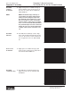
NOTE NOTE: The special bolts required for use
with the relief or shuttle valve (24) end
cover assembly (2) are longer than the
bolts required with standard and cover
assembly. Refer to the individual service
parts lists or parts list charts for correct
service part number if replacement is
required.
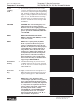
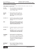
Torque the
valve plugs
24. Torque the two shuttle valve plug assem-
blies (21) in end cover assembly to 9-12 ft.
lbs. (12-16 N m) if cover is so equipped.
SEE FIGURE 69.
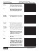
Torque the two relief valve plug assemblies
(21) in end cover assembly to 45-55 ft. lbs.
(61-75 N m) if cover is so equipped.
THE ASSEMBLY OF THE TORQMOTOR™ IS NOW COMPLETE EXCEPT FOR WOODRUFF KEY (12A), NUT
(12B), WASHER (12C), BOLT (12D), LOCKWASHER (12E), RETAINER RING (12F) or PORT O-RINGS (18A) AT
INSTALLATION IF APPLICABLE. PROCEED TO FINAL CHECKS SECTION.
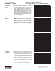
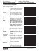
Figure 69A Large Frame Figure 69B Small Frame
Housing
Thrust
Washers
Seal
Shaft
Thrust
Bearing
Backup
Washer
Steel
Washer
Not To Scale
Housing
Thrust
Washers
Seal
Shaft
Thrust
Bearing
Backup
W
Steel
Washer
asher
Not To Scale
Figure 69
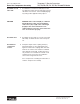
Figure 68
Figure 67
Torqmotor™ Assembly