
Service Manual


HY13-1512-006-M1/USA
Torqmotor™ Service Procedure
TC, TS, TB, TE, TJ, TF, TG, TH and TL Series
Parker Hannifi n Corporation
Hydraulic Pump/Motor Division
Greeneville, TN 37745 US
48
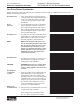
One Piece Stator Construction
A disassembled rotor (8A) stator (8B) and vanes (8C) that cannot be readily assembled by hand can be assem-
bled by the following procedures.
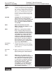
Assemble stator
1. Place stator (8B) onto wear plate (9) with
seal ring (4) side down, after following Torq-
motor™ assembly procedures 1 through
13. Be sure the seal ring is in place. SEE
FIGURE 70.
Insert
two bolts
2. If assembly alignment studs are not being
utilized, align stator bolt holes with wear
plate and housing bolt holes and turn two
bolts (1) fi nger tight into bolt holes approxi-
mately 180 degrees apart to retain stator
and wear plate stationary.
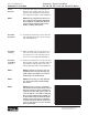
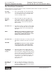
Assemble rotor
3. Assemble the rotor (8A), counterbore down
if applicable, into stator (8B), and onto wear
plate (9) with rotor splines into mesh with
drive link (10) splines. SEE FIGURE 71.
NOTE NOTE: If the manifold side of the rotor
was etched during Torqmotor disassem-
bly, this side should be up. If the rotor is
not etched and does not have a coun-
terbore, use the drive link spline contact
pattern apparent on the rotor splines to
determine the rotor side that must be
against the wear plate.
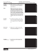
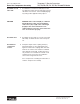
Assemble vanes
CAUTION
Assemble full
complement
of vanes
Remove two
assembled bolts
4. Assemble six vanes (8C), or as many vanes
that will readily assemble into the stator
vane pockets. SEE FIGURE 72.
CAUTION: Excessive force used to push
the rotor vanes into place could shear
off the coating applied to the stator vane
pockets.
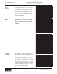
5. Grasp the output end of coupling shaft (12)
with locking pliers or other appropriate
turning device and rotate coupling shaft,
drive link and rotor to seat the rotor and the
assembled vanes (8C) into stator (8B), cre-
ating the necessary clearance to assemble
the seventh or full complement of seven
vanes. Assemble the seven vanes using
minimum force. SEE FIGURE 73.
6. Remove the two assembled bolts (1) if used
to retain stator and wear plate.
Go to Torqmotor™ assembly procedure
#15, to continue Torqmotor™ assembly.
Figure 73
Figure 72
Figure 71
Figure 70
Rotor Set Component Assembly