Form No. 3324–313 Dingor 320–D Compact Utility Loader Model No. 22303—200000001 to 200000500 Parts Catalog Ordering Replacement Parts To order replacement parts, please supply: the part number, the quantity, and the description of each part desired. Understanding Reference Numbers Each identified part in an illustration has a reference number. The reference number for a part also appears in the parts list, along with other information about the part.
3324–313 Contents Description Page Frame and Loader Arm Assembly . . . . . . . . . . . . . 3 Radiator Mount Assembly . . . . . . . . . . . . . . . . . . . . 4 Pump and Fan Mount Assembly . . . . . . . . . . . . . . . 5 Engine Assembly . . . . . . . . . . . . . . . . . . . . . . . . . . . . 6 Fuel Tank and Air Filter Assembly . . . . . . . . . . . . . 7 Hydraulic Tank Assembly . . . . . . . . . . . . . . . . . . . . . 8 Hydraulic Motor Assembly . . . . . . . . . . . . . . . . . . . .
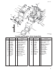
324–313 Sheet No.:2 C–2870 Frame and Loader Arm Assembly Ref. No. 1 2 3 3:2 3:8 4 4:2 4:3 4:4 *4:5 4:6 4:7 5 6 7 8 8:1 * Part No. 32144–70 99–3020–01 99–3154 98–4871 93–6686 100–8814 32144–70 98–4871 93–9367 100–1701 98–4862 100–8822 302–5 99–5105 99–1414 98–4690 302–5 Qty.
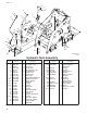
3324–313 Sheet No.:4 C–2872 Radiator Mount Assembly Ref. No. 1 2 3 4 5 5:2 6 7 8 9 10 11 12 13 14 15 16 17 19 4 Part No. 32144–70 3256–82 322–1 32144–14 100–2190 93–6681 93–2048 94–1348 93–2049 71–3383 92–2379 99–5042 2412–34 99–1446–01 3256–23 99–5132 99–5125 66–3240 99–5043 Qty.
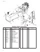
3324–313 Sheet No.:5 C–2873 Pump and Fan Mount Assembly Ref. No. 1 2 3 4 5 6 7 8 9 10 11 12 13 14 16 16:1 17 18 19 19:1 20 21 21:1 *21:2 22 * Part No. Qty.
3324–313 Sheet No.:6 Engine Assembly Ref. No. Part No. Qty.
3324–313 Sheet No.:7 C–2874 Fuel Tank and Air Filter Assembly Ref. No. * Part No. Qty.
3324–313 Sheet No.:8 C–2875 Hydraulic Tank Assembly Ref. No. 8 Part No. Qty.
3324–313 Sheet No.:10 C–2877 Hydraulic Motor Assembly Ref. No. Part No. 1 1:1 1:2 2 3 340–7 237–65 237–80 99–3012 99–3010 8 1 1 2 2 4 5 5:1 5:2 6 7 *7:1 8 8:1 8:2 9 10 11 12 13 14 15 16 99–3011 340–153 237–79 237–151 99–3022 98–9050 98–2712 340–155 237–79 237–151 99–3027 99–3024 99–3029 99–3025 99–3028 99–3023 99–3026 340–72 2 2 1 1 1 2 1 10 1 1 1 1 1 1 1 1 1 4 16:1 237–65 * Qty.
3324–313 Sheet No.:11 C–2878 Hydraulic Cylinder Assembly Ref. No. Part No. Qty.
3324–313 Sheet No.:A1 Hydraulic Cylinder No. 100–4163 Ref. No. Part No. {1 {2 {3 {4 {5 {6 {7 {8 {9 {10 * 99–3065 * { Qty. 1 1 1 1 1 1 1 2 1 2 1 Description Ref. No. Part No. Qty. Description Washer–Backup PSP Seal Rod–Wiper Washer–Backup O–Ring Polypak Wear Ring Wear Ring O–Ring Washer–Backup Seal Kit (Incl. Ref.
3324–313 Sheet No.:12 C–2879 Rear Cover Assembly Ref. No. Part No. Qty.
3324–313 Sheet No.:14 C–2881 Electrical Components Assembly Ref. No. Part No. Qty.
3324–313 Sheet No.:15 C–2882 Decal Assembly Ref. No. Part No. Qty.
3324–313 Sheet No.:19 Wheel and Motor Assembly Ref. No. 1 2 *2:1 2:2 2:3 3 4 4:1 4:2 5 *5:1 5:2 5:3 6 7 8 * Part No. 242–50 98–2747 232–27 98–2748 98–2749 99–3139 99–3064 99–3053–03 10–6830 99–1447 232–27 98–2748 98–2749 99–3052 99–3171 3234–27 Qty. 20 2 1 1 1 4 4 1 5 2 1 1 1 4 4 16 Description Ref. No. Part No. Qty.
3324–313 Sheet No.:A2 Hydraulic Motor Assembly No. 99–3052 Ref. No. *1 2 3 4 * 16 Part No. 94–8178 99–3090 99–3091 3257–42 Not illustrated Qty. 1 1 7 1 Description Kit–Seal,Wheel Motor Shaft–Coupling Screw–Cap. Hex Hd Key–Woodruff Ref. No. Part No. Qty.
3324–313 12 33 16 32 4 31 13 14 15 29 18 16:1 16:2 10 11 10 9 37 9 34:1 34:2 D C 30 18:1 18 27 8 42 4 17 9 5 25 9 18:2 28 7 34 20 3 4 30 C E B 24 24:123 22 21 18 D A 20 4:1 6:1 6 6:2 4:2 19 3 38 3:1 E 21:2 18 21:1 2 26 35:2 35 1 35:1 39 26 B A 39 40 36 Sheet No.:20 41 Hydraulic Valve Assembly Ref. No. 1 2 3 3:1 4 4:1 4:2 5 6 6:1 6:2 7 8 9 10 11 12 13 14 15 16 16:1 16:2 17 18 Part No. Qty.
3324–313 12 33 16 32 4 31 10 13 14 15 29 18 16:1 16:2 11 10 9 37 9 34:1 34:2 D C 30 18:1 18 27 8 42 4 17 9 5 25 9 18:2 28 7 34 20 3 4 30 C E B 24 24:123 22 21 18 D A 20 4:1 6:1 6 6:2 4:2 19 3 38 3:1 E 21:2 18 21:1 2 26 35:2 35 1 35:1 39 26 B A 39 40 36 Sheet No.:20 41 Hydraulic Valve Assembly (Continued) Ref. No. 35:2 36 37 38 39 40 41 42 18 Part No. 237–80 3256–22 99–3079–03 340–159 3256–23 3296–29 3296–42 354–79 Qty.
3324–313 Sheet No.:A3 C–2834 Hydraulic Valve Assembly No. 99–3070 Ref. No. Part No. 1 99–3074 2 99–3075 {3 {4 * 99–4390 * { Qty. 4 6 8 1 1 Description Ref. No. Part No. Qty. Description Gasket Gasket O–Ring O–Ring Seal Kit (Incl. Ref.
3324–313 Sheet No.:A4 C–2759 Hydraulic Valve Assembly No. 99–3073 Ref. No. Part No. *1 98–9097 *2 98–9098 * 20 Not Illustrated Qty. Description 1 Seal Kit Handle Kit Ref. No. Part No. Qty.
3324–313 c–2835 Hydraulic Valve Assembly No. 99–3072 Ref. No. 1 2 {3 4 5 6 * * { Part No. 99–3074 99–3075 100–8807 100–8806 100–8829 99–4391 Qty. Description 1 2 2 1 2 1 1 Gasket Gasket O–Ring Operator ASM Screw–Operator Boot–Operator Seal Kit (Incl. Ref.#3) Ref. No. Part No. Qty.
3324–313 c–2836 Hydraulic Valve Assembly No. 99–3077 Ref. No. 1 2 {3 {4 5 6 7 * * { 22 Part No. 99–3074 99–3075 100–8807 100–8806 100–8829 99–4391 Qty. 1 1 1 2 1 2 1 1 Not illustrated Not Serviced Seperately Description Gasket Gasket O–Ring O–Ring Operator ASM Screw–Operator Boot–Operator Seal Kit (Incl. Ref.# 3 & 4) Ref. No. Part No. Qty.
3324–313 Electrical Schematic WIRE COLOR CODES KUBOTA DINGO SCHEMATIC KEY SWITCH P/N 111216 SW5 IGNITION 4 2 1 5 3 A B S I R T R Y I R A KEY SW BLACK BROWN BLUE GREEN GREY ORANGE PK R T VIO W Y PINK RED TAN VIOLET WHITE YELLOW PK VIO F3 NOTE: SOME WIRE COLORS CHANGE AT REGULATOR CONNECTOR. BK 10A F1 B B A VIO 30A S OFF NO CONNECTION ON B+R+I+A START B+R+I+S HEADLIGHT CONNECTOR BK BN BU GN GY OR F2 VIO 6 VIO 25A RED 5 PK PK YELLOW REG.
3324–313 CBV2 CBV2 M2 99–3077 98–9050 CBV1 CBV1 EX 5 PSI Crack 92–5821 99–4702 P2 P1 54–0110 M CF 98–4735 RV1 LOADER L L M3 M1 SD4 DRIVE R R M4 98–9050 BUCKET RV2 98–4698 98–4699 SD4 99–3077 98–4699 AUX 98–4698 Hydraulic Schematic DISPLACEMENT AND PRESSURE CHART COMPONENT COMPONENT DISPLACEMENT CU IN/REV CU CM/REV PRESSURE PSI FLOWRATE* BARS LPM P1 0.55 CU IN 9 CC 8.5 32.1 P2 0.24 CU IN 4 CC 3.7 14.0 M1, M3 29.1 CU IN 476 CC M2, M4 29.
3324–313 Sheet No.:2 Crankcase Assembly Ref. No. Part No. Qty. 1 2 3 4 5 6 7 8 9 10 11 12 13 14 15 16 17 18 19 20 21 22 100–2167 100–2019 100–2020 98–9398 98–7540 98–7487 98–7488 100–1851 98–9375 98–9377 98–7506 98–9387 100–2051 100–1991 98–7509 98–9436 100–2002 100–2003 100–1923 100–1893 98–7658 100–1779 1 3 5 2 5 3 1 1 2 2 1 2 2 1 1 1 1 1 3 1 1 1 Description Ref. No. Part No. Qty.
3324–313 Sheet No.:3 Oil Pan Assembly Ref. No. Part No. Qty. 1 2 3 4 5 100–2239 98–9350 100–2001 100–2205 98–7585 1 18 1 1 1 26 Description Pan–Oil, Comp, Bolt Strainer–Oil Internal O–Ring Bolt Ref. No. Part No. Qty.
3324–313 Sheet No.:4 Cylinder Head Assembly Ref. No. Part No. Qty. 1 2 3 4 5 6 7 8 9 10 11 *12 98–7531 98–7526 100–2246 98–9395 98–9389 98–7540 100–1882 100–1883 100–1820 100–2043 98–7509 98–2651 2 2 1 1 2 1 3 3 14 1 1 1 Description Ref. No. Part No. Qty. Description Engine–Hook Bolt Head–Cylinder, Comp.
3324–313 Sheet No.:5 Gear Case Assembly Ref. No. Part No. Qty. 1 2 3 4 5 6 7 8 9 10 11 12 13 14 15 16 17 18 100–2048 98–7546 100–1910 98–9388 100–1926 100–2004 100–1894 100–1792 100–1954 98–7605 100–2201 100–1922 100–1766 100–1767 100–2206 100–1971 100–2060 100–2061 1 2 1 1 1 1 1 1 1 1 8 5 1 1 3 1 1 1 19 20 21 22 98–7571 98–7572 98–9367 100–1892 3 3 3 1 28 Description Case–Gear, Comp.
3324–313 Sheet No.:6 Head Cover Assembly Ref. No. Part No. Qty. 1 2 3 4 5 6 7 8 9 10 11 12 13 14 15 16 100–1972 100–1877 100–1878 100–1881 100–1879 100–2040 100–1880 100–1973 98–7739 98–7660 100–2029 100–2030 98–7655 98–7654 98–9449 99–3446 1 1 1 1 1 2 1 1 1 2 1 1 3 3 1 1 Description Ref. No. Part No. Qty.
3324–313 6 4 1 5 3 2 Sheet No.:7 Dipstick and Guide Assembly Ref. No. Part No. Qty. 1 2 3 4 5 6 100–2247 100–2241 98–9374 100–2248 100–1774 100–2229 1 1 1 1 1 1 30 Description Gauge–Oil Oil Gauge Guide ASM O–Ring Support–Guide, Gauge Bolt–Flange Plug–Rubber Ref. No. Part No. Qty.
3324–313 8 6 5 4 7 5 . 6 3 9 2 13 1 11 12 10 14 14 Sheet No.:8 Main Bearing Case Assembly Ref. No. Part No. 1 100–1988 2 100–1757 3 100–1929 4 100–2233 5 6 7 8 9 10 100–1875 100–2055 100–1876 98–7568 100–1750 100–1987 11 100–1757 12 100–2027 13 100–1757 14 100–1874 Qty. Description Ref. No. Part No. Qty.
3324–313 9 10 . 14 15 14 11 10 13 2 12 1 8 6 5 4 3 7 Sheet No.:9 Camshaft Assembly Ref. No. Part No. Qty. 1 2 3 4 5 6 7 8 9 10 11 12 13 14 15 100–1990 100–1989 100–2162 98–7449 100–2163 98–9378 100–1887 98–9350 100–2240 100–1966 100–1968 100–1970 100–1969 100–1967 98–9351 6 6 1 1 1 1 1 2 1 1 1 1 1 1 3 32 Description Tappet Rod–Push Camshaft ASM Screw–Set Gear–Camshaft Key–Feather Stopper–Camshaft Bolt Idle Gear ASM Gear–Idle, Comp.
24–313 2 23 1 . 2 . 4 9 4 12 1 10 11 3 4 6 5 18 8 18 7 14 19 15 20 22 21 13 17 19 16 Sheet No.:10 Piston and Crankshaft Assembly Ref. No. Part No. Qty. 1 1 2 2 3 4 5 6 7 8 100–1994 100–1996 100–2158 100–2159 100–1995 100–1835 100–1998 100–1997 100–1999 100–1942 3 3 3 3 3 6 3 3 6 3 8 100–1943 3 8 9 10 11 12 13 14 15 100–2000 100–2161 100–2160 100–1791 100–2054 100–1891 100–1752 100–1944 3 1 1 3 1 1 1 1 15 100–1947 1 15 100–1948 1 Description Piston (STD.) Piston (+0.
3324–313 Sheet No.:11 Flywheel Assembly Ref. No. Part No. Qty. 1 2 3 4 5 6 7 8 100–2034 100–2156 100–1930 100–2234 98–9359 100–2177 98–7585 98–7660 1 1 5 1 10 1 1 1 34 Description Flywheel–Comp. Gear–Ring Bolt–Flywheel Plate–End, Rear Bolt Cover Bolt Washer–Plain Ref. No. Part No. Qty.
3324–313 Sheet No.:12 Fuel Camshaft Assembly Ref. No. Part No. Qty. 1 2 3 4 5 6 7 8 9 10 11 12 13 14 100–2031 100–1965 100–1795 100–2006 100–1752 100–1903 100–1904 100–1790 100–1843 100–1793 100–1794 100–1784 100–1888 98–9350 1 1 1 1 1 1 1 32 1 8 1 1 1 2 Description Ref. No. Part No. Qty. Description Fuel Camshaft ASM Camshaft Bearing–Ball Gear–Pump, Injection Key,Feather Sleeve–Governor Case–Ball, Governor Ball Cir–Clip, Gov.
3324–313 Sheet No.:13 Engine Stop Lever Assembly Ref. No. Part No. Qty. 1 2 3 4 5 6 7 8 9 10 100–1898 100–1899 100–1846 100–1901 98–7428 100–1902 100–1900 100–2175 98–7654 98–9441 1 1 1 1 2 1 1 1 2 1 36 Description Idle Apparatus ASM Adj. Bolt ASM Nut Nut–Cap Gasket Cap Bolt–Adjusting Nut–Lock Gasket Nut–Cap Ref. No. Part No. Qty.
3324–313 Sheet No.:14 Injection Pump Assembly Ref. No. Part No. Qty. 1 2 3 4 5 6 100–1928 100–1842 100–2217 100–1759 98–9456 98–9457 1 1 2 1 1 1 7 98–9458 8 9 10 11 98–9361 98–9438 98–9440 98–9367 1 2 2 2 4 Description Ref. No. Part No. Qty. Description Joint–Eye Fuel Pipe ASM Clip–Pipe Inj. Pump ASM Shim Shim–Injection (0.25mm) Shim–Injection (0.
3324–313 Sheet No.:15 Injection Pump (Complete Parts) Ref. No. Part No. Qty.
3324–313 Sheet No.:16 Governor Assembly Ref. No. Part No. Qty. 1 2 3 4 5 6 7 8 9 10 11 12 100–1911 100–2059 100–1981 100–2241 100–1905 100–1907 100–1908 100–1751 100–1845 100–2204 100–1909 100–1763 1 1 1 1 1 1 1 1 1 1 1 2 Description Ref. No. Part No. Qty. Description Spring–Start Spring, Governor Assy Lever, Fork Lever–Fork, Comp.
3324–313 Sheet No.:17 Speed Control Plate Assembly Ref. No. Part No. Qty. 1 2 3 4 5 6 7 8 9 10 11 12 13 14 100–1912 100–1914 98–7605 100–1769 98–7654 100–2172 100–1915 100–2208 100–1986 100–1925 100–2050 100–2173 100–1751 100–2207 1 1 2 2 2 1 1 1 1 2 1 1 1 1 40 Description Plate–Cont., Speed Gasket Bolt Bolt Gasket Lever–Governor Collar O–Ring Lever–Cont., Speed Nut Shaft–Lever Lever–Stop, Engine Pin–Spring O–Ring Ref. No. Part No. Qty.
3324–313 Sheet No.:18 Nozzle Holder and Glow Plugs Assembly Ref. No. Part No. Qty. 1 2 3 4 5 6 7 8 9 10 11 12 13 14 15 16 100–1960 98–9420 98–7671 98–9431 98–7654 100–1758 98–7676 98–7677 100–2011 100–2013 100–2036 98–7682 98–7683 98–7684 100–1854 100–2037 1 1 2 1 1 3 3 3 1 1 1 2 2 2 3 1 Description Ref. No. Part No. Qty.
3324–313 2 8 3 11 1 4 6 10 11 T-0.900mm 11 T-1.950mm 5 9 7 Sheet No.:19 Nozzle Holder (Complete Parts) Ref. No. Part No. Qty.
3324–313 2 8 3 11 1 4 6 10 11 T-0.900mm 11 T-1.950mm 5 9 7 Sheet No.:19 Nozzle Holder (Complete Parts Continued) Ref. No. 11 11 11 11 11 11 Part No. 98–7877 98–7878 98–7879 98–7880 98–7881 98–7882 Qty. 1 1 1 1 1 1 Description Ref. No. Part No. Qty. Description Washer – Adj. (1.825) Washer – Adj. (1.850) Washer – Adj. (1.875) Washer – Adj. (1.900) Washer – Adj. (1.925) Washer – Adj. (1.
3324–313 Sheet No.:20 Fuel Pump (Mechanical) Ref. No. Part No. 1 100–2232 2 98–9636 3 98–7692 44 Qty. Description 1 Fuel Pump ASM 1 Gasket–Pump, Fuel 2 Bolt Ref. No. Part No. Qty.
3324–313 21 Sheet No.:21 Dynamo and Pulley Assembly Ref. No. Part No. Qty. 1 2 3 4 5 6 7 8 9 10 11 12 13 14 15 16 17 18 19 20 21 100–2168 100–2214 98–7697 100–1771 98–7660 98–7739 98–7535 100–1782 98–7692 100–1921 100–2039 100–1978 100–1979 98–7611 100–2057 100–2058 100–2056 98–9699 98–9701 98–9702 100–1773 1 1 1 1 2 1 1 1 2 1 1 1 1 1 1 1 1 6 2 2 4 Description Ref. No. Part No. Qty.
3324–313 Sheet No.:22 Dynamo (Complete Parts) Ref. No. Part No. Qty. 1 2 3 4 5 6 7 8 9 10 11 12 13 14 15 16 17 18 100–2168 100–1862 100–2228 100–1860 100–2184 100–1756 100–1867 100–1866 100–1848 100–1865 100–1861 100–1756 100–1868 100–1864 100–1844 100–1847 100–1850 100–1849 1 1 1 1 1 2 1 1 2 1 1 1 1 1 1 1 1 1 46 Description Dynamo ASM Rotor–Comp. Pulley Rotor Collar Bearing–Ball Shaft–Fan Stator–Comp.
3324–313 5 Sheet No.:23 Starter Assembly Ref. No. Part No. Qty. 1 2 3 4 5 100–2179 100–7438 98–7739 98–7535 99–1434 1 2 1 1 1 Description Ref. No. Part No. Qty.
3324–313 Sheet No.:24 Starter (Complete Parts) Ref. No. Part No. Qty.
3324–313 Sheet No.:25 Oil Switch and Thermoswitch Assembly Ref. No. Part No. 1 99–3582 2 98–7764 3 100–2170 Qty. Description Ref. No. Part No. Qty.
3324–313 11 13 7 10 8 8 9 12 1 3 2 4 6 5 Sheet No.:26 Water Flange and Thermostat Assembly Ref. No. Part No. Qty. 1 2 3 4 5 6 7 8 9 10 11 12 13 100–2165 100–2166 98–9580 100–1919 98–7692 100–1977 100–2017 98–9579 100–1789 100–2053 100–1920 100–1869 98–9353 1 1 1 1 2 1 1 2 1 1 1 1 2 50 Description Flange–Water, Comp. Flange–Water Pipe–Return, Water Gasket–Flange, Water Bolt Bolt Pipe–Return, Water Band–Pipe Plug Thermostat ASM Cover–Thermostat Gasket–Thermostat Bolt Ref. No. Part No.
3324–313 Sheet No.:27 Water Pump Assembly Ref. No. Part No. Qty. 1 2 3 4 100–2065 100–1933 100–1934 99–3518 1 1 1 1 5 6 7 8 9 100–2067 100–1932 100–1976 100–1750 100–1764 1 1 1 4 1 Description Ref. No. Part No. Qty.
3324–313 Sheet No.:28 Water Pipe Assembly Ref. No. Part No. Qty. 1 2 3 4 5 100–1918 100–1975 100–1924 100–2203 100–1753 1 1 1 1 2 52 Description Pipe, Water Pipe, Water Stud Nut–Flange Clamp, Hose Ref. No. Part No. Qty.
3324–313 Sheet No.:29 Valve and Rocker Arm Assembly Ref. No. Part No. Qty.
3324–313 Sheet No.:30 Inlet Manifold Assembly Ref. No. Part No. Qty. 1 2 3 4 5 100–2235 100–1937 98–7605 100–1765 100–2236 1 1 2 3 1 54 Description Manifold, Inlet Gasket, In–Manifold Bolt Bolt Inlet Manifold ASM Ref. No. Part No. Qty.
3324–313 Sheet No.:31 Exhaust Manifold Assembly Ref. No. Part No. Qty. 1 2 3 4 5 6 100–2244 100–1957 100–1775 100–2202 100–1778 100–2238 1 1 3 3 3 1 Description Ref. No. Part No. Qty.
3324–313 Sheet No.:32 Gasket Kit Ref. No. Part No. Qty.
3324–313 Maintenance Record Date 57
3324–313 Maintenance Record Date 58
3324–313 Maintenance Record Date 59