Form No.
Introduction Thank you for purchasing a Toro product. All of us at Toro want you to be completely satisfied with your new product, so feel free to contact your local Authorized Service Dealer for help with service, genuine replacement parts, or other information you may require. Whenever you contact your Authorized Service Dealer or the factory, always know the model and serial numbers of your product.
Contents Safety . . . . . . . . . . . . . . . . . . . . . . . . . . . . . . . . . Safe Operating Practices . . . . . . . . . . . . . . Slope Chart . . . . . . . . . . . . . . . . . . . . . . . . . Safety and Instruction Decals . . . . . . . . . . Assembly . . . . . . . . . . . . . . . . . . . . . . . . . . . . . . Loose Parts . . . . . . . . . . . . . . . . . . . . . . . . . Installing the Valve Lever . . . . . . . . . . . . . Activating the Battery . . . . . . . . . . . . . . . . Specifications . . . . . .
Safety Improper use or maintenance by the operator or owner can result in injury. To reduce the potential for injury, comply with these safety instructions and always pay attention to the safety alert symbol, which means CAUTION, WARNING, or DANGER—“personal safety instruction.” Failure to comply with the instruction may result in personal injury or death. Safe Operating Practices This product is capable of amputating hands and feet. Always follow all safety instructions to avoid serious injury or death.
Safety • Do not carry a load with the arms raised. Always carry loads close to the ground. Do not step off of the platform with the load raised. • Do not over-load the attachment and always keep the load level when raising the loader arms. Logs, boards, and other items could roll down the loader arms, injuring you. • Never jerk the control levers; use a steady motion. • Keep your hands, feet, hair, and loose clothing away from any moving parts. • Operate only in daylight or good artificial light.
Safety • Keep all movements on slopes slow and gradual. Do not make sudden changes in speed or direction. • Avoid starting or stopping on a slope. If tires lose traction, proceed slowly, straight down the slope. • • Avoid turning on slopes. If you must turn, turn slowly and keep the heavy end of the traction unit uphill. • Do not operate near drop-offs, ditches, or embankments. The traction unit could suddenly turn over if a wheel goes over the edge of a cliff or ditch, or if an edge caves in.
Safety • Stop and inspect the equipment if you strike an object. Make any necessary repairs before restarting. • Use only genuine replacement parts to ensure that original standards are maintained. • Battery acid is poisonous and can cause burns. Avoid contact with skin, eyes, and clothing. Protect your face, eyes, and clothing when working with a battery. • Battery gases can explode. Keep cigarettes, sparks and flames away from the battery.
Safety Slope Chart M-4402 6
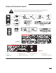
Safety Safety and Instruction Decals Safety decals and instructions are easily visible to the operator and are located near any area of potential danger. Replace any decal that is damaged or lost. 4 7 1 6 # 93-6680 # 93-7814 8 5 2 # 93-9084 3 # 98-8219 # 85-4730 # 98-8235 # 98-4682 9 # 98–8220 # 93-6681 5 # 100–6141 # 98-4677 # 98-9051 # 99-3157 Figure 1 1. Fast 2. Traction drive 3. Slow 4. Entanglement hazard 5. Stay away from moving parts 6. Use only diesel fuel 7. Lift point 8.
Assembly Loose Parts Note: Use the chart below to verify that all parts have been shipped. DESCRIPTION QTY. Traction Unit 1 Valve Lever 1 Key 2 USE Install valve lever Start engine Installing the Valve Lever Activating the Battery 1. The traction unit is shipped with a dry battery. Bulk electrolyte with 1.260 specific gravity must be purchased from a local battery supply outlet. Thread the lever into the speed selector valve (Fig. 2). Note: 2.
Assembly 3. Lift the battery off of its platform. 4 2 POTENTIAL HAZARD • Battery electrolyte contains sulfuric acid which is a deadly poison and it causes severe burns. 3 1 WHAT CAN HAPPEN • If you drink electrolyte you could die, or, if it gets onto your skin, you will be burned. HOW TO AVOID THE HAZARD • Do not drink electrolyte and avoid contact with skin, eyes or clothing. Wear safety glasses to shield your eyes and rubber gloves to protect your hands.
Assembly 10. Install the battery onto its platform (Fig. 3). 11. Secure the battery in the chassis with the bars and nuts removed previously (Fig. 3). 12. Connect the positive (red) cable to the positive (+) battery post (Fig. 3). Slide the rubber cover over the battery post. 13. Connect the negative (black) cable to the negative (–) battery post (Fig. 3). Note: Ensure that the battery cables do not contact any sharp edges or each other. 14. Install the battery cover (Fig. 3).
Specifications Note: Specifications and design are subject to change without notice.
Check Before Operating Stability Data The following table lists the maximum slope recommended for the traction unit in the positions listed in the table. Slopes over the listed degree may cause the traction unit to become unstable. The data in the table assumes that the loader arms are fully lowered and that the factory installed tires are on the traction unit, inflated to the recommended pressure; raised arms and other tire types or pressure may affect the stability.
Before Operating Before operating, check the fuel and oil level, remove debris from the traction unit, and check the tire pressure. Also, ensure that the area is clear of people and debris. You should also know and have marked the locations of all utility lines. 5. Install the fuel tank cap securely. Wipe up any fuel that may have spilled. If possible, fill the fuel tank after each use. This will minimize possible buildup of condensation inside the fuel tank.
Check Before Operating Draining Water from the Fuel Filter Drain water or other contaminants from the fuel filter daily. 1. Stop the engine and remove the key. 2. Open the rear access cover; refer to Opening the Rear Access Cover, page 27. 3. Turn the drain valve until the water runs out of the filter (Fig. 6). Note: The fuel filter is located near the bottom of the fuel tank. 3. Open the rear access cover; refer to Opening the Rear Access Cover, page 27. 4. Clean around the oil dipstick (Fig.
Check Before Operating Checking the Cooling System The cooling system is filled with a 50/50 solution of water and permanent ethylene glycol anti–freeze. Check the level of coolant at the beginning of each day, before starting the engine. 1 m–4591 Figure 8 1. Filler Cap POTENTIAL HAZARD • Coolant is hot and pressurized. WHAT CAN HAPPEN • Discharge of hot pressurized coolant can cause severe burns.
Check Before Operating 9. Remove and store the cylinder locks (refer to Using the Cylinder Locks, page 22), and lower the loader arms. Checking the Hydraulic Fluid Check the hydraulic fluid level before the engine is first started and after every 25 operating hours. 7. If the level is low, add enough fluid to raise it to the proper level. 8. Install the cap on the filler neck. 9. Install the front access cover. 10.
Operation Traction Unit Overview Figure 11 contains a front and back view of the traction unit. Familiarize yourself with all of the traction unit components listed in Figure 11. 6 17 14 4 15 14 5 6 4 13 12 3 2 7 11 10 m-4592 8 1 16 9 m-4599 Figure 11 1. 2. 3. 4. 5. Mount plate Tilt cylinder Auxiliary hydraulic couplers Loader arms Front access cover 6. 7. 8. 9. Fuel tank Wheel Lift cylinder Operator platform POTENTIAL HAZARD • The operator could fall off of the platform.
Operation Controls Become familiar with all the controls (Fig. 12) before you start the engine and operate the traction unit. 3 1 5 2 4 To turn, move the lever located on the side you want to turn back toward the neutral position while keeping the other lever engaged. The farther you move the traction control levers in either direction, the faster the traction unit will move in that direction. To slow or stop, move the traction control levers to neutral. 6 7 m–4388 Figure 12 1. 2. 3. 4.
Operation Move the speed selector lever to the slow (turtle) position to set the auxiliary hydraulics to high speed and the traction drive, loader arms, and attachment tilt to low speed. more hydraulic flow you divert to the auxiliary hydraulics, the slower the traction unit hydraulics will move. Note: POTENTIAL HAZARD • If the speed selector lever is moved while the traction unit is in motion, the traction unit will either stop suddenly or accelerate quickly.
Operation the trencher does work best if you set it close to nine o’clock so that the traction unit will creep slowly when trenching. Note: The flow divider control can be fixed in place by turning the knob on the control clockwise until it contacts the dial (Fig. 13). Indicator Lights The indicator lights warn you in the case of a system malfunction and, in the case of the glow plug light, indicate that the glow plugs are on. Figure 14 illustrates the four indicator lights. 1 3 2 down.
Operation Note: A warm or hot engine may be started without waiting for the light to turn off. IMPORTANT: Do not engage the starter for more than 10 seconds at a time. If the engine fails to start, allow a 30 second cool-down period between attempts. Failure to follow these instructions can burn out the starter motor. 6. Move the throttle lever to the desired setting. IMPORTANT: If the engine is run at high speeds when the hydraulic system is cold (i.e.
Operation Moving a Non-functioning Traction Unit Using the Cylinder Locks IMPORTANT: Never tow or pull the traction unit. Rotating the wheels manually will cause damage to the hydraulic wheel motors. 1. Stop the engine. 2. Lift the traction unit off the ground, using the two lift points (Fig. 15), and move it onto a trailer. POTENTIAL HAZARD • The loader arms may lower when in the raised position. WHAT CAN HAPPEN • Anyone under the loader arms may be injured or crushed.
Operation Removing/Storing the Cylinder Locks IMPORTANT: Before installing the attachment, ensure that the mount plates are free of any dirt or debris. 1. Start the engine. 2. Raise the loader arms to the fully raised position. 3. Stop the engine. 4. 1. Position the attachment on a level surface with enough space behind it to accommodate the traction unit. Remove the clevis pin and cotter pin securing each cylinder lock. 2. Move the speed selector lever to the turtle position. 5.
Operation 1 2 POTENTIAL HAZARD • Hydraulic fluid escaping under pressure can penetrate skin and cause injury. 2 m–4056 WHAT CAN HAPPEN • Fluid accidentally injected into the skin must be surgically removed within a few hours by a doctor familiar with this form of injury or gangrene may result. Figure 19 1. Quick attach pins (shown in engaged position) 2. Cam collars HOW TO AVOID THE HAZARD • Keep body and hands away from pin hole leaks or nozzles that eject high pressure hydraulic fluid.
Operation 2. Stop the engine. 3. Disengage the quick attach pins by turning them to the outside. 4. If the attachment uses hydraulics, move the auxiliary hydraulics lever forward, backward, and back to neutral to relieve pressure at the hydraulic couplers. 5. If the attachment uses hydraulics, slide the collar back on the hydraulic couplers and disconnect them. IMPORTANT: Connect the attachment hoses together to prevent hydraulic system contamination during storage. 6.
Maintenance Service Interval Chart 8 Hours 25 Hours 75 Hours 150 Hours Grease the traction unit Check engine oil level Check radiator coolant level Check for loose fasteners Check tire pressure (20 psi) Clean primary air filter1 Check hydraulic y oil level Inspect hydraulic lines for leaks Change engine oil1, 2 Ch k b Check battery tt electrolyte l t l t llevell Check battery cable connections Check wheel lug nut torque (50 ft.
Maintenance POTENTIAL HAZARD • If you leave the key in the ignition switch, someone could start the engine. WHAT CAN HAPPEN • Accidental starting of the engine could seriously injure you or other bystanders. HOW TO AVOID THE HAZARD • Remove the key from the ignition switch and and disconnect negative battery cable from battery before you do any maintenance. Opening the Access Covers 1 2 Removing the Front Access Cover 1.
Maintenance 2 1 m-4597 Figure 21 1. Rear access cover 2. Locking tabs m–4396 4. When finished, close the rear access cover by swinging it up and seating it in place. Secure it with the two locking tabs. Figure 22 Greasing the Traction Unit Grease all pivot joints every 8 operating hours and immediately after every washing. m–4056 Figure 23 Grease Type: General-purpose grease. 1. Lower the loader arms and stop the engine. Remove the key. 2. Clean the grease fittings with a rag. 3. 4.
Maintenance Removing the Filter 1. Lower the loader arms and stop the engine. Remove the key. 2. Open the rear access cover; refer to Opening the Rear Access Cover, page 27. 3. Release the latches on the air cleaner and pull the air cleaner cover off of the air cleaner body (Fig. 24). 4. 5. 6. Clean the inside of the air cleaner cover with compressed air. Gently slide the primary filter out of the air cleaner body (Fig. 24). Avoid knocking the filter into the side of the body.
Maintenance 4. Install the air cleaner cover with the side indicated as UP facing up and secure the latches (Fig. 24). 5. Close the rear access cover. POTENTIAL HAZARD • Components will be hot if the traction unit has been running. Servicing the Engine Oil WHAT CAN HAPPEN • Touching hot components can cause burns. Change oil after the first 50 operating hours and then every 75 operating hours thereafter.
Maintenance 11. Replace the fill cap. 7. Fill the crankcase with the proper type of new oil; refer to Changing the Oil, page 30. 8. Close the rear access cover. 12. Close the rear access cover. Changing the Oil Filter Replace the oil filter every 150 hours or every other oil change. Note: Change the oil filter more frequently when operating conditions are extremely hot, dusty, or sandy. Servicing the Battery Check the electrolyte level in the battery every 75 hours.
Maintenance Adding Water to the Battery 3. Install the filler caps after the battery is fully charged. The best time to add distilled water to the battery is just before you operate the traction unit. This lets the water mix thoroughly with the electrolyte solution. 4. Replace the battery cover. 1. Clean the top of the battery with a paper towel. 2. Lift off the filler caps (Fig. 27). 3. Slowly pour distilled water into each battery cell until the level is up to the lower part of the tube (Fig.
Maintenance 12. Check the fluid level in the hydraulic tank (refer to Checking the Hydraulic Fluid, page 16) and add fluid to raise the level to the mark on the dipstick. Do not over fill the tank. 7. Install the drain plug. 8. Fill the hydraulic tank with Toro Hy-Pro, Mobil Fluid 424, or equivalent; refer to Checking the Hydraulic Fluid, page 16. 1 Note: 2 9. Install the front access cover 10.
Maintenance 1. Lower the loader arms and stop the engine. Remove the key. 2. Shut off the fuel valve on the bottom of the fuel tank (Fig. 31). 3. Open the rear access cover; refer to Opening the Rear Access Cover, page 27. 4. Open the drain valve (Fig. 29) and drain the fuel from the fuel filter into a suitable container and dispose of it properly. 5. Remove the fuel filter with a filter wrench (Fig. 29).
Maintenance Draining the Fuel Tank Note: Now is the best time to install a new fuel filter because the fuel tank is empty. 7. Install the fuel line onto the fuel filter. POTENTIAL HAZARD • In certain conditions fuel is extremely flammable and highly explosive. 8. Slide the hose clamp close to the fuel filter to secure the fuel line. WHAT CAN HAPPEN • A fire or explosion from fuel can burn you, others, and cause property damage. 9. Close the rear access cover.
Maintenance 10. Paint all scratched or bare metal surfaces. Paint is available from your Authorized Service Dealer. 11. Check anti–freeze protection and fill the radiator with a 50/50 solution of water and permanent ethylene glycol anti–freeze. 12. Store the traction unit in a clean, dry garage or storage area. Remove the key from the ignition switch and keep it in a memorable place. 13. Cover the traction unit to protect it and keep it clean.
Troubleshooting PROBLEM The starter does not crank. The engine cranks, but will not start. POSSIBLE CAUSES CORRECTIVE ACTION 1. The electrical connections are corroded or loose. 1. Check the electrical connections for good contact. 2. A fuse is blown or loose. 2. Correct or replace the fuse. 3. The relay or switch is damaged. 3. Contact your Authorized Service Dealer. 4. The battery is discharged. 4. Charge the battery or replace it. 5. A damaged starter or starter solenoid. 5.
Troubleshooting PROBLEM The engine cranks, but will not start (continued). The engine starts, but does not keep running. 38 POSSIBLE CAUSES CORRECTIVE ACTION 8. Slow cranking speed. 8. Check the battery, oil viscosity and starting motor (contact your Authorized Service Dealer). 9. The air cleaner element is dirty. 9. Clean or replace. 10. Low compression. 10. Contact your Authorized Service Dealer. 11. The injection nozzles are damaged. 11. Contact your Authorized Service Dealer. 12.
Troubleshooting PROBLEM The engine runs, but knocks or misses. The engine will not idle. POSSIBLE CAUSES CORRECTIVE ACTION 1. Dirt, water, stale fuel, or incorrect fuel is in the fuel system. 1. Drain and flush the fuel system; add fresh fuel. 2. Engine overheating. 2. See ENGINE OVERHEATS. 3. There is air in the fuel. 3. Bleed nozzles and check for air leaks at the fuel hose connections and fittings between the fuel tank and engine. 4. The injection nozzles are damaged. 4.
Troubleshooting PROBLEM The engine g overheats. The engine loses power. POSSIBLE CAUSES 1. More coolant is needed. 1. Check and add coolant. 2. Restricted air flow to the radiator. 2. Inspect and clean the radiator screen with every use. 3. The crankcase oil level is incorrect. 3. Fill or drain to the full mark. 4. Excessive loading. 4. Reduce load; use lower ground speed. 5. The thermostat is damaged. 5. Contact your Authorized Service Dealer. 6. The fan belt is loose or broken. 6.
Troubleshooting PROBLEM Excessive black smoke from exhaust. Excessive white smoke from exhaust. Traction unit does not drive. POSSIBLE CAUSES CORRECTIVE ACTION 1. The air cleaner element is dirty. 1. Clean or replace. 2. The injection pump timing is incorrect. 2. Contact your Authorized Service Dealer. 3. Incorrect fuel is in the fuel system. 3. Drain the fuel system and refill with specified fuel. 4. The injection nozzles are damaged. 4. Contact your Authorized Service Dealer. 5.
The Toro Siteworkt Systems Product Line A One-Year Limited Warranty Conditions and Products Covered The Toro Company and its affiliate, Toro Warranty Company, pursuant to an agreement between them, jointly warrant your Toro Sitework Systems Product (“Product”) to be free from defects in materials or workmanship for one year or 500 operational hours, whichever occurs first. Where a warrantable condition exists, we will repair the Product at no cost to you including diagnosis, labor, and parts.