
Operator's Manual


8
Assembly
Loose
Parts
Note: Use the chart below to verify that all parts have been shipped.
DESCRIPTION QTY. USE
T
raction Unit
V
alve Lever
1
1
Install valve lever
Key 2
Start engine
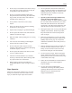
Installing
the V
alve Lever
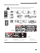
1. Thread the lever into the speed selector valve
(Fig. 2).
Note: The lever should be installed with the
bend toward the operator.
2. Tighten the jam nut on the lever to lock it in
position.
1
m–3883
Figure 2
1. Speed
selector lever
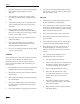
Activating
the Battery
The traction unit is shipped with a dry battery. Bulk
electrolyte with 1.260 specific gravity must be
purchased from a local battery supply outlet.
1. Remove the four bolts securing the battery cover
and remove the cover (Fig. 3)
2. Remove the nuts and bars securing the battery
(Fig. 3).
2
5
3
m–4391
4
1
2
6
7
Figure 3
1. Battery
cover
2. Bolt
3. Battery
4. Bars
5. Nut
6.
Positive cable
7.
Negative cable