FORM NO. 3321–515 DINGO 222 Traction Unit Model No. 22304 – 890001 & Up Operator’s Manual IMPORTANT: Read this manual carefully. It contains information about your safety and the safety of others. Also become familiar with the controls and their proper use before you operate the product.
Introduction Thank you for purchasing a Toro product. All of us at Toro want you to be completely satisfied with your new product, so feel free to contact your local Authorized Service Dealer for help with service, genuine replacement parts, or other information you may require. Whenever you contact your Authorized Service Dealer or the factory, always know the model and serial numbers of your product.
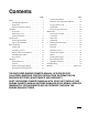
Contents Safety . . . . . . . . . . . . . . . . . . . . . . . . . . . . . . . . . Safe Operating Practices . . . . . . . . . . . . . . Slope Chart . . . . . . . . . . . . . . . . . . . . . . . . . Safety and Instruction Decals . . . . . . . . . . Assembly . . . . . . . . . . . . . . . . . . . . . . . . . . . . . . Loose Parts . . . . . . . . . . . . . . . . . . . . . . . . . Install Valve Lever . . . . . . . . . . . . . . . . . . . Activate the Battery . . . . . . . . . . . . . . . . . . Specifications . .
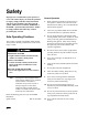
Safety Improper use or maintenance by the operator or owner can result in injury. To reduce the potential for injury, comply with these safety instructions and always pay attention to the safety alert symbol, which means CAUTION, WARNING, or DANGER—“personal safety instruction.” Failure to comply with the instruction may result in personal injury or death. Safe Operating Practices General Operation 1.
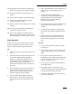
Safety • Follow the manufacturer’s recommendations for wheel weight or counterweights to improve stability. • Use only Toro approved attachments. Attachments can change the stability and the operating characteristics of the machine. Warranty may be voided if used with un–approved attachments. • Keep all movement on slopes slow and gradual. Do not make sudden changes in speed or direction. 18. Use extra care when loading or unloading the machine onto a trailer or truck. • 19.
Safety Children Tragic accidents can occur if the operator is not alert to the presence of children. Children are often attracted to the machine and the work activity. Never assume that children will remain where you last saw them. The following requirements must be followed to prevent injury to children. 1. Keep children out of the work area and under the watchful care of another responsible adult. 2. Be alert and turn the machine off if children enter the area. 3.
Safety Slope Chart Read all safety instructions on pages 2–4.
Safety Safety and Instruction Decals Safety decals and instructions are easily visible to the operator and are located near any area of potential danger. Replace any decal that is damaged or lost. RATED OPERATING CAPACITY 515 LBS. On Loader Cross Bar (Part No. 98–4682) Near Oil Fill (Part No. 85–4730) On Control Panel (Part No. 99–1385) On Front Control Panel (Part No. 98–4677) Inside Left Loader Arm (1) (Part No. 98–9051) On Front Control Panel (Part No. 98–8220) On Front Control Panel (Part No.
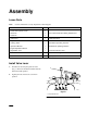
Assembly Loose Parts Note: Use the chart below to verify all parts have been shipped. DESCRIPTION QTY.
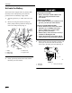
Assembly Activate the Battery The traction unit is shipped with a dry battery. Bulk electrolyte with 1.260 specific gravity must be purchased from a local battery supply outlet. 1. 2. POTENTIAL HAZARD • Battery electrolyte contains sulfuric acid which is a deadly poison and it causes severe burns. Turn the ignition key to ”OFF” and remove the key.
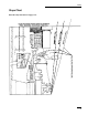
Assembly 5. Leave the covers off and connect a 3 to 4 amp battery charger to the battery posts (Fig. 4). Charge the battery at a rate of 4 amperes or less for 4 hours (12 volts). 8. Install the battery into the chassis (Fig. 2). 9. Secure the battery in chassis with the battery clamp (Fig. 2). 10. Using the bolt and wing nut supplied with the battery, connect the positive (red) cable to the positive (+) battery post (Fig. 2). Slide the rubber cover over the battery post. 4 2 11.
Specifications General Specifications: Approved Attachments (without operator and without attachments) IMPORTANT: Use only Toro approved attachments. Contact your local Toro Dealer for additional approved attachments. Overall width 40.5 inches (103 cm) Overall length 60.0 inches (152 cm) • Standard Bucket Overall height 49.
Before Operating the filler neck. This space in the tank allows gasoline to expand. Do not fill the fuel tank completely full. Each time before operating your machine, check the following: • Fuel level • Engine oil level • Remove debris from machine • Tire pressure • Drive chain condition • Be sure the work area is clear of other people and children. • 3. Be sure the work area is clear of debris and all utility line locations are know and clearly marked.
Check Before Operating Checking Oil Level Remove Debris From Machine 1. Park the machine on a level surface, lower the loader arms and turn the ignition key to “OFF” to stop the engine. Remove the key. 2. Clean around the oil dipstick (Fig. 5) so dirt cannot fall into the filler hole and damage the engine. 3. 4. Pull out the oil dipstick and wipe the metal end clean (Fig. 5). Slide the oil dipstick fully into the filler tube (Fig. 5). Pull the dipstick out and look at the metal end.
Check Before Operating Check Hydraulic Fluid Check the hydraulic fluid level before engine is first started and after every 25 operating hours. Fluid Type: Mobil Fluid 424 (ISO 46) or equivalent anti–wear hydraulic fluid. IMPORTANT: Use only group 1 hydraulic oils specified. Other fluids could cause system damage. 1 Group 1 Hydraulic Fluid (Recommended for ambient temperatures consistently below 100 F.
Operation Think Safety First Please carefully read all the safety instructions on pages 2–8 and view the training video. Following these instructions could help you or bystanders avoid injury. Choke To start engine, close carburetor choke by moving the control lever forward to the ON position. After engine starts, regulate choke to keep engine running smoothly. As soon as possible, open the choke by moving the control lever rearward to the OFF position. A warm engine requires little or no choking.
Operation Attachment tilt lever Flow divider control To tilt attachment forward, slowly push the attachment tilt lever forward. Move flow divider control to twelve–o’clock position (normal operating position) for no flow division. When moving control to nine–o’clock position, flow is diverted to the attachments and less is available to the wheels and loader arms. This allows for greater concentration of power where it’s needed most.
Operation Starting and Stopping Engine Starting 1. Stand on platform. 2. Move the auxiliary hydraulics valve lever to neutral. POTENTIAL HAZARD • Attachment may move during starting WHAT CAN HAPPEN • Operator or bystander may be injured by attachment HOW TO AVOID THE HAZARD • Make sure auxiliary hydraulic lever is in neutral position during engine starting. 3. Move the throttle control midway between “SLOW” and “FAST” positions before starting a cold engine. 4.
Operation Driving Forward or Backward Stopping the Machine The throttle control regulates the engine speed as measured in rpm (revolutions per minute). Place the throttle control in the “FAST” position for best performance. To stop the machine, move the traction control levers to neutral, lower loader arms to the ground, and turn the ignition key to “OFF” to stop the engine. Remember to remove the key from the key switch. Note: Throttle position can be utilized to operate at slower speeds. Forward 1.
Operation Moving A Non Functioning Machine IMPORTANT: Never tow the machine because hydraulic damage may occur. To Move the Machine 1. Turn the ignition key to “OFF” to stop the engine. 2. Lift entire machine off the ground and move machine. Using Cylinder Locks IMPORTANT: Normal maintenance should be completed with loader arms lowered. If maintenance or repair requires the loader arms raised, use the cylinder locks. POTENTIAL HAZARD • Loader arms may lower when in the raised position.
Operation Attachments 7. Move the auxiliary hydraulics lever to the forward, backward and back to neutral position to relieve hydraulic pressure at the hydraulic couplers. 8. Remove protective covers from hydraulic couplers on machine. Connect covers together to prevent contamination during operation. 9. Slide collar back on hydraulic coupler and connect attachment couplers to machine couplers. Connecting IMPORTANT: Use only Toro approved attachments.
Operation Transporting and Securing IMPORTANT: Do not operate or drive machine on roadways. IMPORTANT: When transporting machine on a trailer, always use the following procedure: 1. Lower the loader arms. 2. Turn the ignition key to “OFF” to stop the engine. 3. Secure the machine to the trailer with chains or straps using the rear platform support openings to secure rear of machine and loader arms/mount plate to secure front of machine.
Maintenance Service Interval Chart Service Operation Each Use Hydraulic Fluid–check level Initial 8 Hours 25 Hours 50 Hours 100 Hours 200 Hours X Hydraulic Fluid–change X Hydraulic Filter–change Engine Oil—check level 400 Hours Initial X X Engine Oil—change* X Engine Oil Filter–change (200 hours or every other oil change) X Traction Drive Chain Tension–check Initial Wheel Nuts–tighten Initial X Traction Drive Chain–lubrication X Chassis—grease** X Foam Air Cleaner—service* X X
Maintenance POTENTIAL HAZARD • If you leave the key in the ignition switch, someone could start the engine. WHAT CAN HAPPEN • Accidental starting of the engine could seriously injure you or other bystanders. HOW TO AVOID THE HAZARD • Remove the key from the ignition switch and and disconnect negative battery cable from battery before you do any maintenance. Air Cleaner 1 Foam Element: Clean and re-oil after every 25 operating hours. 3 4 5 Paper Element: Replace after every 100 operating hours.
Maintenance Engine Oil Cleaning the Foam Element 1. Wash the foam element in liquid soap and warm water. When the element is clean, rinse it thoroughly. 2. Dry the element by squeezing it in a clean cloth (do not wring). 3. Put one or two ounces of oil on the element (Fig. 11). Squeeze the element to distribute the oil. IMPORTANT: Replace the foam element if it is torn or worn. Change oil after every 100 operating hours.
Maintenance Changing/Draining Oil Change Oil Filter 1. Start the engine and let it run five minutes. This warms the oil so it drains better. Replace the oil filter every 200 hours or every other oil change. 2. Park the machine so that the drain side is slightly lower than the opposite side to ensure that the oil drains completely. Then lower the loader arms, chock the wheels and turn the ignition key to “OFF” to stop the engine. Remove the key. 3. 4.
Maintenance Spark Plug Checking the Spark Plug Check the spark plug(s) after every 200 operating hours. Make sure the air gap between the center and side electrodes is correct before installing the spark plug. Use a spark plug wrench for removing and installing the spark plug(s) and a gapping tool/feeler gauge to check and adjust the air gap. Install a new spark plug(s) if necessary. 1. IMPORTANT: Never clean the spark plug(s).
Maintenance Greasing and Lubrication Fuel Filter Grease all pivot joints every 25 operating hours. Grease every 8 hours when operating conditions are extremely dusty or sandy and immediately after every washing. Replace the fuel filter after every 200 operating hours or yearly, whichever occurs first. Grease Type: General-purpose grease. How to Grease 1. 2. 3. 4. Lower the loader arms and turn the ignition key to “OFF” to stop the engine. Remove the key.
Maintenance Fuel Tank Draining The Fuel Tank Hydraulic System Replacing the Hydraulic Filter Change the hydraulic filter: POTENTIAL HAZARD • In certain conditions gasoline is extremely flammable and highly explosive. WHAT CAN HAPPEN • A fire or explosion from gasoline can burn you, others, and cause property damage. • After the first 8 operating hours. • After every 400 operating hours. 1.
Maintenance Check Hydraulic Lines 1 After every 100 operating hours, check hydraulic lines and hoses for leaks, loose fittings, kinked lines, loose mounting supports, wear, weather and chemical deterioration. Replace all moving hydraulic hoses every 1500 hours or 2 years, which ever come first. Make necessary repairs before operating. 2 3 Figure 17 1. Hydraulic filter 2. Gasket 3. Adapter Changing the Hydraulic Fluid Change the hydraulic fluid: • After the first 8 operating hours.
Maintenance Traction Drive Chains IMPORTANT: Under sandy conditions, sand can build up on the sprockets. This enlarges the sprocket and the chain tightens. Under these conditions the chains should have 2–1/2 to 3–1/2 inches of slack between the bottom of the chain guard and the lower chain span. Checking the Tension Check the drive chain tension before using the traction unit for the first time and every 50 hours of use thereafter.
Maintenance IMPORTANT: In sandy conditions, an additional 1/2 inch of slack may improve chain performance. 3 Checking Electrolyte Level 1. Open covers to see into the cells. The electrolyte must be up to the lower part of the tube (Fig. 21). Do not allow the electrolyte to get below the plates. (Fig. 21). 2. If the electrolyte is low, add the required amount of distilled water; refer to Adding Water to the Battery, page 30. 1 2 m–3961 1 Figure 20 1. Mud guard 2. 3” x 3” block of wood 7. 3.
Maintenance 1. Check the electrolyte level; refer to Checking Electrolyte Level, page 30. 2. Remove the filler caps from the battery and connect a 3 to 4 amp battery charger to the battery posts. Charge the battery at a rate of 4 amperes or less for 4 hours (12 volts). Do not overcharge the battery. Install the filler caps after the battery is fully charged. POTENTIAL HAZARD • Charging the battery produces gasses. WHAT CAN HAPPEN • Battery gasses can explode.
Maintenance Electrical Schematic F1 30A RED B IGNITION S GND M WHITE START RELAY GREEN 3 G 4 2 R BLACK BLACK WHITE BLUE GREEN VIOLET RED START OFF B+R B+S M+G IGNITION SWITCH RUN ENGINE SCHEMATIC MAG START OIL REG B+ AC AC SPARK PLUG OIL SWITCH – + IGNITION MODULES SOLINOID SHIFT STARTER SPARK PLUG SOLINIOD FUEL 32 5 1 GREEN AUX.
Maintenance Hydraulic Schematic 33
Troubleshooting PROBLEM Starter does not crank Engine g will not start,, starts hard,, or f il to fails t keep k running. i Engine g loses power. p Engine g overheats. Abnormal vibration. 34 POSSIBLE CAUSES CORRECTIVE ACTION 1. Auxiliary hydraulics lever is not in neutral position. 1. Move lever to neutral position. 2. Battery is dead. 2. Charge the battery. 3. Electrical connections are corroded or loose. 3. Check electrical connections for good contact. 4.
Troubleshooting PROBLEM Machine does not drive. POSSIBLE CAUSES CORRECTIVE ACTION 1. Flow divider valve lever is in 9 o’clock position. 1. Move lever to the 12 to 10 o’clock position. 2. Hydro fluid level low. 2. Add hydro fluid to reservoir. 3. Traction pump drive coupler is loose or broken. 3. Contact Service Dealer. 4. Pump and/or wheel motor is defective or damaged. 4. Contact Service Dealer. 5. Control valve is defective or damaged. 5. Contact Service Dealer. 6.
The Toro SiteWorkT Systems Product Line One Year Limited Warranty The Toro Company warrants your Toro SiteWorkT Systems Product (Product") to be free from defects in materials or workmanship for the period of time listed below. Where a warrantable condition exists, Toro will repair the Product at no cost to you including diagnosis, labor, parts, and transportation. This warranty begins on the date the Product is delivered to the original retail purchaser.