Form No.
Introduction Thank you for purchasing a Toro product. All of us at Toro want you to be completely satisfied with your new product, so feel free to contact your local Authorized Service Dealer for help with service, genuine replacement parts, or other information you may require. Whenever you contact your Authorized Service Dealer or the factory, always know the model and serial numbers of your product.
Contents Safety . . . . . . . . . . . . . . . . . . . . . . . . . . . . . . . . . Safe Operating Practices . . . . . . . . . . . . . . Slope Chart . . . . . . . . . . . . . . . . . . . . . . . . . Safety and Instruction Decals . . . . . . . . . . . Assembly . . . . . . . . . . . . . . . . . . . . . . . . . . . . . . Loose Parts . . . . . . . . . . . . . . . . . . . . . . . . . Installing the Valve Lever . . . . . . . . . . . . . Activating the Battery . . . . . . . . . . . . . . . . Specifications . . . . .
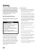
Safety Improper use or maintenance by the operator or owner can result in injury. To reduce the potential for injury, comply with these safety instructions and always pay attention to the safety alert symbol, which means CAUTION, WARNING, or DANGER—“personal safety instruction.” Failure to comply with the instruction may result in personal injury or death.
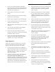
Safety • Do not over-load the attachment and always keep the load level when raising the loader arms. Logs, boards, and other items could roll down the loader arms, injuring you. • Raising the loader arms on a slope will affect the stability of the machine. Whenever possible, keep the loader arms in the lowered position when on slopes. • Never jerk the control levers; use a steady motion. • • Keep your hands, feet, hair, and loose clothing away from any moving parts.
Safety • Do not operate on wet grass. Reduced traction could cause sliding. • Keep nuts and bolts tight. Keep equipment in good condition. • Do not park the traction unit on a hillside or slope without lowering the attachment to the ground and chocking the wheels. • Never tamper with safety devices. Check safety systems for proper operation before each use. • • Do not try to stabilize the traction unit by putting your foot on the ground.
Safety • Keep your body and hands away from pin hole leaks or nozzles that eject high pressure hydraulic fluid. Use cardboard or paper to find hydraulic leaks. Hydraulic fluid escaping under pressure can penetrate skin and cause injury requiring surgery within a few hours by a qualified surgeon or gangrene may result.
Safety Slope Chart Read all safety instructions on pages 2–4.
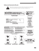
Safety Safety and Instruction Decals Safety decals and instructions are easily visible to the operator and are located near any area of potential danger. Replace any decal that is damaged or lost. RATED OPERATING CAPACITY 515 LBS. On Loader Cross Bar (Part No. 98–4682) Near Oil Fill (Part No. 85–4730) On Control Panel (Part No. 99–1385) On Front Control Panel (Part No. 98–4677) Inside Left Loader Arm (1) (Part No. 98–9051) On Front Control Panel (Part No. 98–8220) On Loader Arms (4) (Part No.
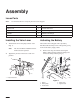
Assembly Loose Parts Note: Use the chart below to verify all parts have been shipped. DESCRIPTION QTY. USE Valve Lever 1 Install valve lever Key 2 Start the engine Oil filter 1 Break–in oil change Chain link 2 Spare parts Installing the Valve Lever Activating the Battery 1. The traction unit is shipped with a dry battery. Purchase bulk electrolyte with 1.260 specific gravity from a local battery supply outlet. Thread the lever into the pump selector valve (Fig. 1). Note: 2.
Assembly 2. Gently push the hydraulic hoses aside and lift the battery out of the chassis. 5. Charge the battery at a rate of 4 amperes or less for 4 hours (12 volts). 4 POTENTIAL HAZARD • Battery electrolyte contains sulfuric acid which is a deadly poison and it causes severe burns. 2 3 1 WHAT CAN HAPPEN • If you drink electrolyte you could die or if it gets onto your skin you will be burned. HOW TO AVOID THE HAZARD • Do not drink electrolyte and avoid contact with skin, eyes or clothing.
Assembly 8. Install the battery into the chassis (Fig. 2). 9. Secure the battery in the chassis with the battery clamp, strip, and wing nut (Fig. 2). 10. Using the bolt and wing nut supplied with the battery, connect the positive (red) cable to the positive (+) battery post (Fig. 2). Slide the rubber cover over the battery post. 11. Using the bolt and wing nut supplied with the battery, connect the negative (black) cable to the negative (–) battery post (Fig. 2).
Specifications General Specifications Attachments Overall width 40.5 inches (103 cm) Overall length 60.0 inches (152 cm) Overall height 49.0 inches (125 cm) Weight 1565 lbs (710kg) Rated operating capacity (with 200 lb operator) 515 lbs (234 kg) Tipping capacity (with 200 lb operator) l030lbs (467kg) Wheelbase 28.5 inches (72 cm) Dump height (with std. bucket) 48.75 inches (124 cm) Reach – fully raised (with std. bucket) 26.0 inches Height to hinge pin 66.
Check Before Operating Stability Data The following table lists the maximum slope recommended for the traction unit in the positions listed in the table. Slopes over the listed degree may cause the traction unit to become unstable. The data in the table assumes that the loader arms are fully lowered and that the factory installed tires are on the traction unit, inflated to the recommended pressure; raised arms and other tire types or pressure may affect the stability.
Before Operating Before operating, check the fuel and oil level, remove debris from the traction unit, and check the tire pressure. Also, ensure that the area is clear of people and debris. You should also know and have marked the locations of all utility lines. Adding Fuel POTENTIAL HAZARD • When fueling, under certain circumstances, a static charge can develop, igniting the gasoline. WHAT CAN HAPPEN • A fire or explosion from gasoline can burn you, others, and cause property damage.
Check Before Operating Filling the Fuel Tank 1. Park the traction unit on a level surface, lower the loader arms, and stop the engine. 2. Remove the key and allow the engine to cool. 3. Clean around the fuel tank cap and remove it. 4. Add unleaded regular gasoline to each fuel tank, until the level is 1/4 to 1/2 inch (6 mm to 13 mm) below the bottom of each filler neck. IMPORTANT: This space in the tank allows gasoline to expand. Do not fill the fuel tank completely full. 5.
Check Before Operating Removing Debris from the Traction Unit Use only Group 1 ISO type 46/68 anti–wear hydraulic fluids, recommended for ambient temperatures consistently below 100 F, such as Toro Hy-Pro, Mobil Fluid 424, or other equivalent fluid. IMPORTANT: Operating the engine with a blocked grass screen, dirty or plugged cooling fins, and/or cooling shrouds removed, will result in engine damage from overheating. 1.
Check Before Operating Tire Pressure Maintain the air pressure in the tires as specified. Check the tires when they are cold to get the most accurate reading. Pressure: 20–30 psi Note: Use a lower tire pressure (20 psi) when operating in sandy soil conditions to provide better traction in the loose soil. 1 m–1872 Figure 7 1.
Operation To stop the engine, rotate the key to the off position. Throttle Lever POTENTIAL HAZARD • Operator could fall off platform. Move the control forward to increase the engine speed and rearward to decrease speed. WHAT CAN HAPPEN • Operator could be seriously injured. HOW TO AVOID THE HAZARD • Do not move any of the control levers unless standing with both feet on the platform and hands holding the hand grips. Controls Become familiar with all the controls (Fig.
Operation Loader Arm Lever To lower the loader arms, slowly push the loader arm lever forward. To raise the loader arms, slowly pull the loader arm lever rearward. Auxiliary Hydraulics Lever To operate a hydraulic attachment in forward direction, slowly pull the auxiliary hydraulics lever rearward. To operate a hydraulic attachment in reverse direction, slowly push the auxiliary hydraulics lever forward.
Operation 1 2 5 Starting the Engine 3 4 Figure 9 1. Flow divider control 2. Knob 3. 12 o’clock position • Starting and Stopping the Engine 4. 10 to 11 o’clock position 5. 9 o’clock position Move the flow divider control to the twelve–o’clock position to provide maximum speed to the traction unit hydraulics. 1. Stand on the platform. 2. Move the auxiliary hydraulics valve lever to neutral. 3. Move the throttle lever midway between slow (turtle) and fast (rabbit) positions. 4.
Operation Stopping the Engine 1. Move the throttle lever to the slow (turtle) position. 2. Lower the loader arms to the ground. 3. Turn the ignition key off. Note: Stopping the Traction Unit To stop the traction unit, move the traction control levers to neutral and the throttle lever to slow (turtle), lower loader arms to the ground, and turn the ignition key off to stop the engine. Remove the key.
Operation Using the Cylinder Locks 7. Slowly lower the loader arms until cylinder locks contact the cylinder body and rod end. 8. Stop the engine. POTENTIAL HAZARD • The loader arms may lower when in the raised position. Removing/Storing the Cylinder Locks 1. Start the engine. WHAT CAN HAPPEN 2. Raise the loader arms to the fully raised position. injured or crushed. 3. Stop the engine. 4. Remove the clevis pin and cotter pin securing each cylinder lock. 5. Remove the cylinder locks. 6.
Operation the traction unit. The warranty of the traction unit may be voided if used with unapproved attachments. 1 IMPORTANT: Before installing the attachment, ensure that the mount plates are free of any dirt or debris. m–4056 Figure 14 1. Position the attachment on a level surface with enough space behind it to accommodate the traction unit. 2. Move the pump control lever to the turtle position. 3. Start the engine. 4.
Operation POTENTIAL HAZARD • Hydraulic fluid escaping under pressure can penetrate skin and cause injury. WHAT CAN HAPPEN • Fluid accidentally injected into the skin must be surgically removed within a few hours by a doctor familiar with this form of injury or gangrene may result. HOW TO AVOID THE HAZARD • Keep body and hands away from pin hole leaks or nozzles that eject high pressure hydraulic fluid. • Use cardboard or paper to find hydraulic leaks, never use your hands.
Maintenance Service Interval Chart Service Operation Each Use Hydraulic Fluid–check level Initial 8 Hours 25 Hours 50 Hours 100 Hours 200 Hours X Hydraulic Filter–change Engine Initial X X Oil—change1 Initial X Engine Oil Filter–change (200 hours or every other oil change)1 X Wheel Nuts–tighten Initial Traction Drive Chain—lubricate X Chassis—grease2 Foam Air Filter—clean1 Paper Air Filter—replace1 X X X Spark Plug(s)—check X Engine RPM (idle & full throttle)—check X Gasoline
Maintenance POTENTIAL HAZARD • If you leave the key in the ignition switch, someone could start the engine. WHAT CAN HAPPEN • Accidental starting of the engine could seriously injure you or other bystanders. HOW TO AVOID THE HAZARD • Remove the key from the ignition switch and and disconnect negative battery cable from battery before you do any maintenance. Servicing the Air Cleaner 1 Foam Element: Clean and oil after every 25 operating hours.
Maintenance Cleaning the Foam Element Servicing the Engine Oil 1. Wash the foam element in liquid soap and warm water. When the element is clean, rinse it thoroughly. 2. Dry the element by squeezing it in a clean cloth (do not wring). 3. Put one or two ounces of oil on the element (Fig. 16). Squeeze the element to distribute the oil. IMPORTANT: Replace the foam element if it is torn or worn. Change oil after the first 25 operating hours and then every 100 operating hours thereafter.
Maintenance Changing/Draining Oil 1. Start the engine and let it run five minutes. This warms the oil so it drains better. 2. Park the traction unit so that the drain side is slightly lower than the opposite side to ensure that the oil drains completely. 3. Lower the loader arms, chock the wheels, stop the engine, and remove the key. 1 m–3216 Figure 17 1. Oil drain valve POTENTIAL HAZARD • Components will be hot if the traction unit has been running.
Maintenance Changing the Oil Filter Servicing the Spark Plugs Replace the oil filter every 200 hours or every other oil change. Note: 1. Change the oil filter more frequently when operating conditions are extremely dusty or sandy. Drain the oil from the engine; refer to Changing/Draining Oil, page 27. 2. Remove the old filter and wipe the filter adapter (Fig. 18) gasket surface. 3. Apply a thin coat of new oil to the rubber gasket on the replacement filter (Fig. 18).
Maintenance Checking the Spark Plugs 1. Greasing and Lubrication Look at the center of the spark plugs (Fig. 20). If you see light brown or gray on the insulator, the engine is operating properly. A black coating on the insulator usually means the air cleaner is dirty. IMPORTANT: Replace the spark plugs when they have a black coating, worn electrodes, an oily film, or cracks. Do not attempt to clean a spark plug. 2. Check the gap between the center and side electrodes (Fig. 20).
Maintenance Replacing the Fuel Filter Draining the Fuel Tank Replace the fuel filter after every 200 operating hours or yearly, whichever occurs first. POTENTIAL HAZARD • In certain conditions gasoline is extremely flammable and highly explosive. Replacing the Fuel Filter Do not re-install a dirty filter. WHAT CAN HAPPEN Lower the loader arms, stop the engine, and remove the key. • A fire or explosion from gasoline can burn 2. Shut off the fuel valve on the bottom of the fuel tank. 3.
Maintenance Servicing the Hydraulic System Replacing the Hydraulic Filter 6. Start the engine and let run for about two minutes to purge air from the system. 7. Stop the engine and check for leaks. 8. Check the fluid level in the hydraulic tank and add enough oil to raise the level to mark on dipstick. Change the hydraulic filter: • After the first 8 operating hours. • After every 200 operating hours. Changing the Hydraulic Fluid 1.
Maintenance 4. POTENTIAL HAZARD • Hydraulic fluid escaping under pressure can penetrate skin and cause injury. Measure the distance between the bottom of the chain guard and the lower chain span (Fig. 23). If the slack in the chain is not within 1–1/2 to 2–1/2 inches (3.8 to 6.35 cm), adjust the tension (refer to Adjusting the Tension).
Maintenance a solution of four parts water and one part baking soda. Apply a light coating of grease to the battery terminals to reduce corrosion. 1 2 Voltage: 12 v, 380 Cold Cranking Amps Checking the Electrolyte Level 3 4 m–3963 Figure 24 1. Axle retaining bracket 2. Nut 1. Clean the top of the battery with a paper towel. 2. Lift off the filler caps (Fig. 25). 3. Check the electrolyte level. The electrolyte should be up to the lower part of the tube (Fig. 25).
Maintenance 2. Remove the filler caps from the battery and connect a 3 to 4 amp battery charger to the battery posts. 3. Charge the battery at a rate of 4 amperes or less for 4 hours (12 volts). Do not overcharge the battery. POTENTIAL HAZARD • Charging the battery produces gasses. WHAT CAN HAPPEN • Battery gasses can explode. HOW TO AVOID THE HAZARD • Keep cigarettes, sparks and flames away 3. Service the air cleaner; refer to Servicing the Air Cleaner, page 25. 4.
Maintenance B. Run the engine to distribute conditioned fuel through the fuel system (5 minutes). C. Stop the engine, allow it to cool and drain the fuel tank; refer to Draining Fuel Tank, page 30. D. Restart the engine and run it until it stops. E. Choke the engine. F. Start and run the engine until it will not start again. G. Dispose of fuel properly. Recycle as per local codes. IMPORTANT: Do not store stabilizer/conditioned gasoline over 90 days. 13.
Troubleshooting PROBLEM Starter does not crank Engine g will not start,, starts hard,, or f il to keep fails k running. i Engine g loses power. Engine g overheats. Abnormal vibration. 36 POSSIBLE CAUSES CORRECTIVE ACTION 1. Auxiliary hydraulics lever is not in neutral position. 1. Move lever to neutral position. 2. Battery is dead. 2. Charge the battery. 3. Electrical connections are corroded or loose. 3. Check electrical connections for good contact. 4. Relay or switch is defective.
Troubleshooting PROBLEM Machine does not drive. POSSIBLE CAUSES CORRECTIVE ACTION 1. Flow divider valve lever is in 9 o’clock position. 1. Move lever to the 12 to 10 o’clock position. 2. Hydro fluid level low. 2. Add hydro fluid to reservoir. 3. Traction pump drive coupler is loose or broken. 3. Contact Service Dealer. 4. Pump and/or wheel motor is defective or damaged. 4. Contact Service Dealer. 5. Control valve is defective or damaged. 5. Contact Service Dealer. 6.
The Toro Company warrants your Toro SiteWork Systems Product (“Product”) to be free from defects in materials or workmanship for the period of time listed below. Where a warrantable condition exists, Toro will repair the Product at no cost to you including diagnosis, labor, parts, and transportation. This warranty begins on the date the Product is delivered to the original retail purchaser.