Form No. 3324-314 DingoR 322 Traction Unit Model No.
Introduction Thank you for purchasing a Toro product. All of us at Toro want you to be completely satisfied with your new product, so feel free to contact your local Authorized Service Dealer for help with service, genuine replacement parts, or other information you may require. Whenever you contact your Authorized Service Dealer or the factory, always know the model and serial numbers of your product.
Contents Safety . . . . . . . . . . . . . . . . . . . . . . . . . . . . . . . . . Safe Operating Practices . . . . . . . . . . . . . . Slope Chart . . . . . . . . . . . . . . . . . . . . . . . . . Safety and Instruction Decals . . . . . . . . . . Assembly . . . . . . . . . . . . . . . . . . . . . . . . . . . . . . Loose Parts . . . . . . . . . . . . . . . . . . . . . . . . . Installing the Valve Lever . . . . . . . . . . . . . Activating the Battery . . . . . . . . . . . . . . . . Specifications . . . . . .
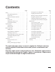
Safety Improper use or maintenance by the operator or owner can result in injury. To reduce the potential for injury, comply with these safety instructions and always pay attention to the safety alert symbol, which means CAUTION, WARNING, or DANGER—“personal safety instruction.” Failure to comply with the instruction may result in personal injury or death. Safe Operating Practices This product is capable of amputating hands and feet. Always follow all safety instructions to avoid serious injury or death.
Safety • Do not carry a load with the arms raised. Always carry loads close to the ground. Do not step off of the platform with the load raised. • Do not over-load the attachment and always keep the load level when raising the loader arms. Logs, boards, and other items could roll down the loader arms, injuring you. • Never jerk the control levers; use a steady motion. • Keep your hands, feet, hair, and loose clothing away from any moving parts. • Operate only in daylight or good artificial light.
Safety • Keep all movements on slopes slow and gradual. Do not make sudden changes in speed or direction. • Avoid starting or stopping on a slope. If tires lose traction, proceed slowly, straight down the slope. • • Avoid turning on slopes. If you must turn, turn slowly and keep the heavy end of the traction unit uphill. Do not operate near drop-offs, ditches, or embankments. The traction unit could suddenly turn over if a wheel goes over the edge of a cliff or ditch, or if an edge caves in.
Safety • Stop and inspect the equipment if you strike an object. Make any necessary repairs before restarting. • Use only genuine replacement parts to ensure that original standards are maintained. • Battery acid is poisonous and can cause burns. Avoid contact with skin, eyes, and clothing. Protect your face, eyes, and clothing when working with a battery. • Battery gases can explode. Keep cigarettes, sparks and flames away from the battery.
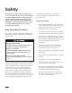
Safety Slope Chart M-4402 6
Safety Safety and Instruction Decals Safety decals and instructions are easily visible to the operator and are located near any area of potential danger. Replace any decal that is damaged or lost. RATED OPERATING CAPACITY 515 LBS. On Loader Cross Bar (Part No. 98–4682) Near Oil Fill (Part No. 85–4730) On Control Panel (Part No. 99-3157) On Front Control Panel (Part No. 98–4677) Inside Left Loader Arm (1) (Part No. 98–9051) On Front Control Panel (Part No. 98–8220) On Loader Arms (4) (Part No.
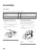
Assembly Loose Parts Note: Use the chart below to verify that all parts have been shipped. DESCRIPTION QTY. USE Traction Unit 1 Valve Lever 1 Key 2 Start engine Hydraulic oil filter 1 Break-in oil change Install valve lever Installing the Valve Lever Activating the Battery 1. The traction unit is shipped with a dry battery. Bulk electrolyte with 1.260 specific gravity must be purchased from a local battery supply outlet. Thread the lever into the speed selector valve (Fig. 1). Note: 2.
Assembly 3. Gently push the hydraulic hoses aside and lift the battery out of the chassis. 5. POTENTIAL HAZARD • Battery electrolyte contains sulfuric acid which is a deadly poison and it causes severe burns. Leave the covers off and connect a 3 to 4 amp battery charger to the battery posts (Fig. 4). Charge the battery at a rate of 4 amperes or less for 4 hours (12 volts). 4 2 3 WHAT CAN HAPPEN • If you drink electrolyte you could die or if it 1 gets onto your skin you will be burned.
Assembly 7. Slowly pour electrolyte into each cell until the level is once again up to the upper line on the battery case (Fig. 3) and install covers. 8. Install the battery into the chassis (Fig. 2). 9. Secure the battery in chassis with the bar and wing nuts removed previously (Fig. 2). 10. Using the bolt and wing nut supplied with the battery, connect the positive (red) cable to the positive (+) battery post (Fig. 2). Slide the rubber cover over the battery post. 11.
Specifications Overall width 40.5 inches (103 cm) Overall length 60.0 inches (152 cm) Overall height 49.0 inches (125 cm) Weight 1567 lbs (711 kg) Rated operating capacity 515 lbs (with 200 lb operator and std. bucket) (234 kg) Tipping capacity l030lbs (with 200 lb operator and st. bucket) (467kg) Wheelbase 28 inches (71 cm) Dump height (with std. bucket) 48.75 inches (124 cm) Reach – fully raised (with std. bucket) 26.0 inches Height to hinge pin 66.
Check Before Operating Stability Data The following table lists the maximum slope recommended for the traction unit in the positions listed in the table. Slopes over the listed degree may cause the traction unit to become unstable. The data in the table assumes that the loader arms are fully lowered and that the factory installed tires are on the traction unit, inflated to the recommended pressure; raised arms and other tire types or pressure may affect the stability.
Before Operating Before operating, check the fuel and oil level, remove debris from the traction unit, and check the tire pressure. Also, ensure that the area is clear of people and debris. You should also know and have marked the locations of all utility lines. Adding Fuel POTENTIAL HAZARD • When fueling, under certain circumstances, a static charge can develop, igniting the gasoline. WHAT CAN HAPPEN • A fire or explosion from gasoline can burn you, others, and cause property damage.
Check Before Operating Filling the Fuel Tanks 1. Park the traction unit on a level surface, lower the loader arms, and stop the engine. 2. Remove the key and allow the engine to cool. 3. Clean around the fuel tank caps and remove them. 4. Use a funnel and add unleaded regular gasoline to each fuel tank, until the level is 1/4 to 1/2 inch (6 mm to 13 mm) below the bottom of each filler neck. IMPORTANT: This space in the tank allows gasoline to expand. Do not fill the fuel tank completely full. 5.
Check Before Operating Removing Debris from the Traction Unit Use only Group 1 ISO type 46/68 anti–wear hydraulic fluids, recommended for ambient temperatures consistently below 100_ F, such as Toro Hy–Pro, Mobil Fluid 424, or other equivalent fluid. IMPORTANT: Operating the engine with a blocked grass screen, dirty or plugged cooling fins, and/or cooling shrouds removed, will result in engine damage from overheating. 1.
Check Before Operating Tire pressure Maintain the air pressure in the tires as specified. Check the tires when they are cold to get the most accurate reading. Pressure: 15–20 psi Note: Use a lower tire pressure (15 psi) when operating in sandy soil conditions to provide better traction in the loose soil. 1 m–1872 Figure 7 1.
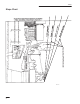
Operation Traction Unit Overview Figure 8 contains a front and back view of the traction unit. Familiarize yourself with all of the traction unit components listed in Figure 8. 14 12 11 3 3 10 5 13 11 9 2 6 8 4 1 7 m–4393/4389 Figure 8 1. 2. 3. 4. Mount plate Tilt cylinder Loader arms Lift cylinder 5. 6. 7. 8. Fuel tank Wheel Operator platform Engine POTENTIAL HAZARD • The operator could fall off of the platform. WHAT CAN HAPPEN • The operator could be seriously injured.
Operation Controls Traction Control Levers Become familiar with all the controls (Fig. 9) before you start the engine and operate the traction unit. To move forward, move the traction control levers forward. To move rearward, move the traction control levers rearward. 5 3 1 2 To go straight, move both traction control levers equally. 4 To turn, move the lever located on the side you want to turn back toward the neutral position while keeping the other lever engaged. 6 8 7 m–4388 Figure 9 1. 2.
Operation Speed Selector Lever Move the speed selector lever to the fast (rabbit) position to set the traction drive, loader arms, and attachment tilt to high speed and the auxiliary hydraulics to low speed. Move the speed selector lever to the slow (turtle) position to set the auxiliary hydraulics to high speed and the traction drive, loader arms, and attachment tilt to low speed. powering attachments; however, the two systems share the same hydraulic pumps. Using the flow divider control (Fig.
Operation that require the nine o’clock position; however, the trencher does work best if you set it close to nine o’clock so that the traction unit will creep slowly when trenching. Note: IMPORTANT: If the engine is run at high speeds when the hydraulic system is cold (i.e., when the ambient air temperature is around freezing or lower), hydraulic system damage could occur.
Operation • To turn, move the lever located on the side you want to turn toward the neutral position while keeping the other lever engaged. • To slow or stop, move the traction control levers to neutral. Note: The farther you move the traction control levers in either direction, the faster the traction unit will move in that direction. Moving a Non-functioning Traction Unit IMPORTANT: Never tow or pull the traction unit. Rotating the wheels manually will cause damage to the hydraulic wheel motors. 1.
Operation Using the Cylinder Locks POTENTIAL HAZARD • The loader arms may lower when in the raised position. WHAT CAN HAPPEN • Anyone under the loader arms may be injured or crushed. HOW TO AVOID THE HAZARD • Always install the cylinder locks when doing maintenance that requires raised loader arms. 2. Raise the loader arms to the fully raised position. 3. Stop the engine. 4. Remove the clevis pin and cotter pin securing each cylinder lock. 5. Remove the cylinder locks. 6. Lower the loader arms.
Operation Installing and Removing Attachments 6. Raise the loader arms while tilting back the mount plate at the same time. IMPORTANT: The attachment should be raised enough to clear the ground, and the mount plate should be tilted all the way back. Connecting an Attachment IMPORTANT: Use only Toro approved attachments. Attachments can change the stability and the operating characteristics of the traction unit. The warranty of the traction unit may be voided if used with unapproved attachments. 7.
Operation Note: When you connect the attachment male connector first, you will relieve any pressure build up in the attachment. POTENTIAL HAZARD • Hydraulic fluid escaping under pressure can penetrate skin and cause injury. WHAT CAN HAPPEN • Fluid accidentally injected into the skin must be surgically removed within a few hours by a doctor familiar with this form of injury or gangrene may result.
Maintenance Service Interval Chart 8 Hours 25 Hours 100 Hours 200 Hours 400 Hours Yearly/Storage Grease the traction unit Check engine g oil level Check for loose fasteners Check tire pressure (20 psi) Clean primary air filter1 Check hydraulic oil level y Inspect hydraulic lines for leaks Change engine oil1, 2 Ch k b tt l t l t llevell Check battery electrolyte Check wheel lug nut torque (50 ft-lbs)3 Check battery cable connections Change engine oil filter (every other oil change)1, 4 Check engine g s
Maintenance POTENTIAL HAZARD • If you leave the key in the ignition switch, someone could start the engine. WHAT CAN HAPPEN • Accidental starting of the engine could seriously injure you or other bystanders. HOW TO AVOID THE HAZARD • Remove the key from the ignition switch and and disconnect negative battery cable from battery before you do any maintenance. Removing/Installing the Hood Removing the Hood 1 Before performing many maintenance procedures, you will need to remove the hood. 1.
Maintenance 1. Lower the loader arms and stop the engine. Remove the key. Servicing the Air Cleaner 2. Clean the grease fittings with a rag. Clean the primary filter every 25 operating hours. Replace the primary and secondary filter yearly. 3. Connect a grease gun to each fitting (Fig 17 and 18). Note: Service the air cleaner more frequently if operating conditions are extremely dusty or sandy. Removing the Filter 1. Lower the loader arms and stop the engine. Remove the key. 2.
Maintenance 4. 1 3 4 Install the air cleaner cover with the side indicated as UP facing up and secure the latches (Fig. 19). Servicing the Engine Oil Change oil after the first 50 operating hours and then every 100 operating hours thereafter. 5 2 m–4387 Note: 1 Change oil more frequently when operating conditions are extremely dusty or sandy. Figure 19 1. Latches 2. Air cleaner cover 3. Air filter body 4. Primary filter 5.
Maintenance 3. Lower the loader arms, chock the wheels, and stop the engine. Remove the key. POTENTIAL HAZARD • Components will be hot if the traction unit has been running. 8. Check the oil level; refer to Checking the Oil Level, page 14. 9. Slowly add additional oil to bring the level to the F (full) mark on the dipstick. 10. Replace the fill cap. Changing the Oil Filter WHAT CAN HAPPEN • Touching hot components can cause burns.
Maintenance 6. 7. Install the replacement oil filter to the filter adapter. Turn the oil filter clockwise until the rubber gasket contacts the filter adapter, then tighten the filter an additional 1/2 turn (Fig. 21). Fill the crankcase with the proper type of new oil; refer to Changing the Oil, page 28. Servicing the Battery Check the electrolyte level in the battery every 100 hours. Always keep the battery clean and fully charged. Use a paper towel to clean the battery case.
Maintenance POTENTIAL HAZARD • Charging the battery produces gasses. WHAT CAN HAPPEN • Battery gasses can explode. 1 HOW TO AVOID THE HAZARD • Keep cigarettes, sparks, and flames away 2 from the battery. m–3876 Figure 23 1. Spark plug wire 2. Spark plug Servicing the Spark Plugs Check the spark plugs after every 200 operating hours. Ensure that the air gap between the center and side electrodes is correct before installing each spark plug.
Maintenance 2 IMPORTANT: Do not substitute an automotive oil filter or severe hydraulic system damage may result. 3 1 5. Place a drain pan under the filter. 6. Remove the old filter and wipe the filter adapter, gasket surface clean. 7. Apply a thin coat hydraulic fluid to the rubber gasket on the replacement filter (Fig. 25). 8. Install the replacement hydraulic filter onto the filter adapter.
Maintenance 14. Remove and store the cylinder locks (refer to Using the Cylinder Locks, page 22) and lower the loader arms. Changing the Hydraulic Fluid Change the hydraulic fluid yearly. 1. Position traction unit on a level surface. 2. Raise the loader arms and install the cylinder locks; refer to Using the Cylinder Locks, page 22. 3. Stop the engine and remove the key. 4. Remove the hood; refer to Removing the Hood, page 26.
Maintenance 5. Place a drain pan under the fuel lines to catch any leaks, then remove the filter from the fuel lines. 6. Install a new filter and move the hose clamps close to the filter. 7. Remove the clamp blocking fuel flow and open the fuel valves. 2. Lower the loader arms and stop the engine. Remove the key. 3. Shut off the fuel valve on the bottom of each fuel tank (Fig. 27). 1 1 m–4390 Figure 27 2 1. Fuel valve m–3217 4.
Maintenance Cleaning and Storage 1. Lower the loader arms and stop the engine. Remove the key. 2. Remove dirt and grime from the external parts of the entire traction unit, especially the engine. Clean dirt and chaff from the outside of the engine’s cylinder head fins and blower housing. IMPORTANT: You can wash the traction unit with mild detergent and water. Do not pressure wash the traction unit. Avoid excessive use of water, especially near the control panel, engine, hydraulic pumps, and motors. 3.
Troubleshooting PROBLEM Starter does not crank Engine g will not start, starts hard, or f il to keep fails k running. i Engine g loses power. Engine g overheats. Abnormal vibration. 36 POSSIBLE CAUSES CORRECTIVE ACTION 1. Auxiliary hydraulics lever is not in neutral position. 1. Move lever to neutral position. 2. Battery is dead. 2. Charge the battery. 3. Electrical connections are corroded or loose. 3. Check electrical connections for good contact. 4. Relay or switch is defective. 4.
Troubleshooting PROBLEM Traction unit does not drive. POSSIBLE CAUSES CORRECTIVE ACTION 1. Flow divider valve lever is in 9 o’clock position. 1. Move lever to the 12 to 10 o’clock position. 2. Hydro fluid level low. 2. Add hydro fluid to reservoir. 3. Traction pump drive coupler is loose or broken. 3. Contact Service Dealer. 4. Pump and/or wheel motor is defective or damaged. 4. Contact Service Dealer. 5. Control valve is defective or damaged. 5. Contact Service Dealer. 6.
The Toro Siteworkt Systems Product Line A One-Year Limited Warranty Conditions and Products Covered The Toro Company and its affiliate, Toro Warranty Company, pursuant to an agreement between them, jointly warrant your Toro Sitework Systems Product (“Product”) to be free from defects in materials or workmanship for one year or 500 operational hours, whichever occurs first. Where a warrantable condition exists, we will repair the Product at no cost to you including diagnosis, labor, and parts.