
Service Manual

23
BDP-10A/16A/21L
25
58 x4
44
40
56 x2
1
Partial View
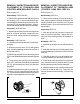
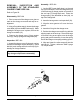
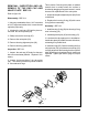
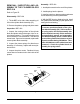
Figure 21. BDP-16A/21L
Inspection BDP-16A/21L
1. Inspect the charge cover O-ring and running
surfaces for damage. Inspect the spring , check
ball (44), and mating seat in the end cap (25) for
damage or foreign material.
2. If damaged or worn, replace O-ring and
gerotor assembly (40), charge spring and charge
ball (44) and end cap (25).
Note: If end cap (25) is to be removed,
delay charge components reassembly.
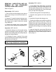
REMOVAL, INSPECTION AND AS-
SEMBLY OF THE STANDARD
CHARGE PUMP BDP-16A/21L
Refer to Figure 21.
Disassembly BDP-16A/21L
1. Prior to removal of the charge cover, place a
mark on the charge cover and end cap for re-
alignment.
2. Using a 1/2” wrench loosen the charge cover
bolts from the BDP end cap (25). While holding
the charge cover in place, remove the charge
cover bolts (56).
3. Remove the charge cover, O-ring, gerotor
items (40), charge spring and charge ball (44).
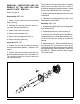
Assembly BDP-16A/21L
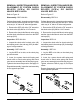
1. Lay the BDP (input shaft down), so the end
cap is horizontal. Place the charge ball in the
end cap (25) charge pocket so it mates to the
end cap (25) charge ball seat. Place the charge
spring on top of the charge ball.
2. Insert the inner gerotor over input shaft (1).
3. Align the outer gerotor to fit over the inner
gerotor.
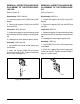
4. Insert the O-ring into the charge cover.
5. Position the charge cover and O-ring with the
aligning mark on the end cap (25). Place the
charge cover and O-ring as one piece over the
charge spring and gerotor assembly. Insure the
spring fits into the charge cover spring retaining
groove.
6. Align and insert the cap screws (56) into the
charge cover. While holding the charge cover in
place tighten the cap screws (56) per Tables 5
and 6, page 16.
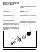
BDP-21L
44
4x 58
25
1
40
56
56
BDP-16A