
Service Manual
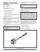

31
BDP-10A/16A/21L
REMOVAL, INSPECTION AND AS-
SEMBLY OF INPUT SHAFT BDP-
10A
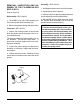
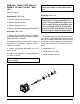
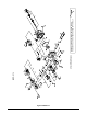
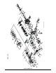
Refer to Figure 31.
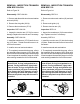
Disassembly BDP-10A
1. Remove the retaining ring (22).
2. Remove the lip seal (20).
3. Remove the spacer (21).
4. Remove the shaft assembly (18) from the BDP.
Inspection BDP-10A
1. Inspect the input shaft (18) for worn splines,
surface damage, or keyway damage. Replace
shaft assembly if necessary.
2. Inspect the bearing (19) for evidence of scor-
ing, corrosion, or damage. Replace shaft as-
sembly if necessary.
3. Inspect and replace the spacer (21) if it is
bent or broken.
4. Inspect and replace the retaining ring (22) if
it is bent or broken.
Note: Replace the input shaft seal (20)
after removal.
Note: If trunnion arm is to be removed,
delay reassembly of input shaft assem-
bly.
Assembly BDP-10A
Note: Upon removal, it is recommended
that all seals, O-rings and gaskets be re-
placed. During installation, lightly lubri-
cate all seals, O-rings and gaskets with
clean petroleum jelly prior to assembly.
Also, protect the inner diameter of seals
by covering the shaft with plastic wrap.
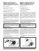
1. Install input shaft assembly (18) into the hous-
ing (1) bore. Light tapping with a rubber mallet
may be necessary on the input shaft (18) once
the bearing is aligned with the housing (1) bore.
Rotate the input shaft (18) to insure free move-
ment.
2. Install spacer (21).
3. Install new lip seal (20).
4. Install retaining ring (22).
18
19
23
21
20
22
1
Figure 31. BDP-10A